• The move to the new server is done. There are some software and database maintenance updates in process. This has us passing the hat around to help out. We appreciate any donations. Seriously, even a dollar helps. The payment page may be found here - https://www.audiokarma.org/support.html

Resurrection of a QRX-9001, or Restoration of a classic.

And yet another year flies by ... <G>

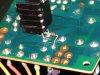
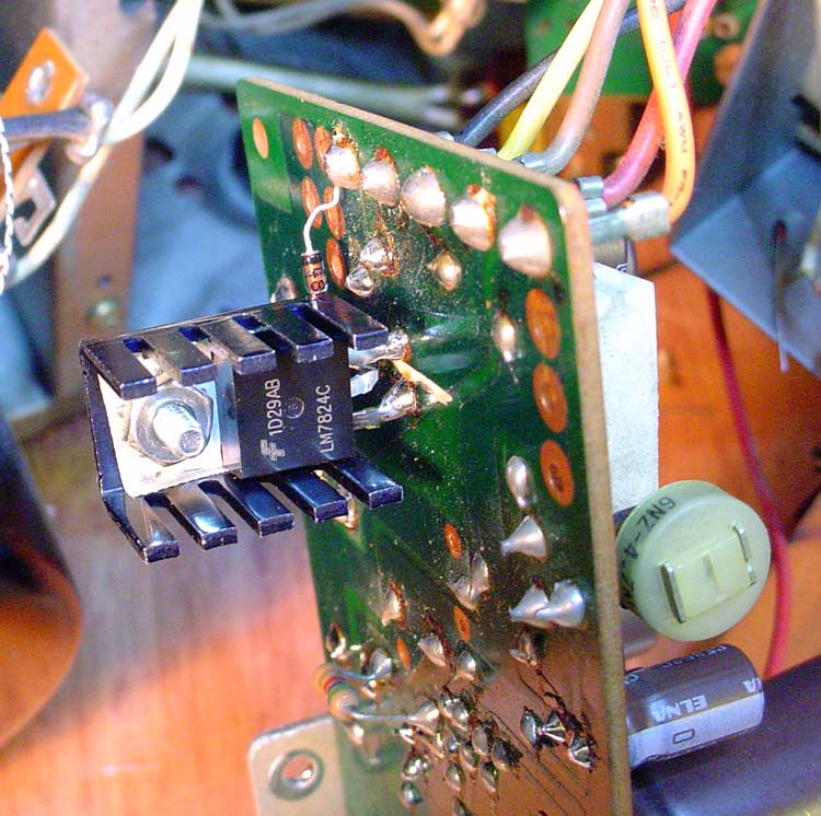
Just to confirm ... to add the regulator, you're cutting the trace to Pin 01? Can't quite make it out on the super closeup you posted - nice pic, but no point of reference that works for me.

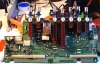
I finally got around to resurrecting my resurrection here. Got all the boards that hide behind the front panel and figure to put that all back together and test the results prior to tackling the rest.

Also, which leg of the regulator goes to which side of the trace? Seems to me, output should go towards the pin ...
 
Last edited:
Long as I'm thinking QRX ... I see mention of a 22uf poly cap as a bypass on the power rails. Can't find any more about the whys and wherefores on that.

22uf seems kind of large - and what power rating? I can see the cap used is Dayton Audio, but they don't carry that value - any more? Anyway, rule of thumb I always figured was a percentage of the primary capacitance of the circuit ... in this case 10000uf X4.
 
Last edited:
And yet another year flies by ... <G>

Just to confirm ... to add the regulator, you're cutting the trace to Pin 01? Can't quite make it out on the super closeup you posted - nice pic, but no point of reference that works for me.

I finally got around to resurrecting my resurrection here. Got all the boards that hide behind the front panel and figure to put that all back together and test the results prior to tackling the rest.

Also, which leg of the regulator goes to which side of the trace? Seems to me, output should go towards the pin ...

You know, I don't remember the exact placement, but I will open it up and get better info for you.

Long as I'm thinking QRX ... I see mention of a 22uf poly cap as a bypass on the power rails. Can't find any more about the whys and wherefores on that.

22uf seems kind of large - and what power rating? I can see the cap used is Dayton Audio, but they don't carry that value - any more? Anyway, rule of thumb I always figured was a percentage of the primary capacitance of the circuit ... in this case 10000uf X4.

That was a typo on my part, it should be 12uf, I used this one

Dayton Audio DMPC-12 12uF 250V

This was per info I received from Jim at QRXrestore
 
It lives! IT LIVES!!

(Old threads never die anyway) :D

Typo is what I figured for the bypass cap on the rail, and glad I checked. I had a feeling that's what had happened. Found this in my wanderings today from one of Jim's posts ...

In this picture I have 4 10,000uf caps silicon glued to the subframe. The + and - connections are down, the ground is up, and I have a 12 uf polypropylene cap across the both banks of caps, from - to +.

http://www.audiokarma.org/forums/showpost.php?p=4470380&postcount=106

Brings to mind another question though ... I was wondering about the attachment points you used for the bypass cap - it wouldn't blow up or anything, but seems to me that would only be filtering part of the rail? :scratch2:

********

On the regulator thing, I was hoping you had a link back to Jim's stuff or a bigger pic - appreciate your offer to dig deeper on that. On the plus side, that should be visible with a quick pop of the top ... :yes:

********

PS ... ever finish yours and get it up and running? I kinda got side tracked with a couple or three other projects. I've got a QRX-6001 for a backup and tossed it into the rack in the meantime - that's been working real well and has the same quad capabilities, so there hasn't been any real rush to get the 9001 done.

(Sorry about the disappearing pics from my prior posts ... now they're here, now they're not ... my web host ISP is busy "improving" my website. I hate that when that happens. Here's the pics uploaded to AK for now.)
 
Last edited:
...Brings to mind another question though ... I was wondering about the attachment points you used for the bypass cap - it wouldn't blow up or anything, but seems to me that would only be filtering part of the rail? :scratch2:

The cap is from the + rail to the - rail (orange - violet). So it should get the whole rail.

On the regulator thing, I was hoping you had a link back to Jim's stuff or a bigger pic - appreciate your offer to dig deeper on that. On the plus side, that should be visible with a quick pop of the top ... :yes:

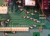
I took some more pics, in the pic pin 1 is at the top, diode is connected to pin 2 and pin 3 is on the bottom.. I cut the trace between pin 1 & 3, kind of looks like a scratch in the pic


PS ... ever finish yours and get it up and running? I kinda got side tracked with a couple or three other projects. I've got a QRX-6001 for a backup and tossed it into the rack in the meantime - that's been working real well and has the same quad capabilities, so there hasn't been any real rush to get the 9001 done.

Yes, for the most part, all that's left is the tuner. I put it aside to restore a Marantz 4230 for my brother. Then dug into a HK 75+, then a Rotel DVD, Kenwood, then... etc. And work is nuts, I have been working at least 1 OT day for most of the last year. And toss in family... The tuner is a little weak compared to other units I have, so I know it needs a little love. Now if I could only find the time :sigh:
 

Attachments

  • Img_3615_1.jpg
    Img_3615_1.jpg
    91.4 KB · Views: 50
Last edited:
Thank you, kind sir ... I vote for YOU for AKer of the year!

You're braver than I am messing with the tuner. That takes some serious skillz AND equipment to do right. Lucky me, mine was working fine before the tear down, and I'm just planning to leave well enough alone on that.

Good tip on the bypass caps on the volume board too. I've got a bunch of the 630v like you used, but I'll add some 250v to the Mouser order.

http://www.mouser.com/Search/ProductDetail.aspx?R=1429-2104virtualkey21980000virtualkey1429-2104

Those are quite a bit smaller (12x13x7 instead of 17x23x10) and should fit nicely. Worse comes to worse, glue some small washers to the bottom panel to stand it off a bit and add some room.

An example of the inter-relatedness of all things ... the Mouser order wasn't big enough to justify the shipping, so I decided to recap my dbx BoomBox also.

Of course, now the order is too much ... <G>

PS ... did you do the dreaded pass thru pins? I'll show you mine if you show me yours!
 
Last edited:
Thank you, kind sir ... I vote for YOU for AKer of the year!

Not me, there are many others who are more deserving.

You're braver than I am messing with the tuner. That takes some serious skillz AND equipment to do right. Lucky me, mine was working fine before the tear down, and I'm just planning to leave well enough alone on that.

Yeah, it is not something I look forward to doing, you need a good AM/FM signal generator, and a scope. Fortunately I have both, just need the time.

Good tip on the bypass caps on the volume board too. I've got a bunch of the 630v like you used, but I'll add some 250v to the Mouser order.

http://www.mouser.com/Search/ProductDetail.aspx?R=1429-2104virtualkey21980000virtualkey1429-2104

Those are quite a bit smaller (12x13x7 instead of 17x23x10) and should fit nicely. Worse comes to worse, glue some small washers to the bottom panel to stand it off a bit and add some room.

I am going to have to order some of those. I left them off, as I didn't want to pull the board again. They are easy to add though.

An example of the inter-relatedness of all things ... the Mouser order wasn't big enough to justify the shipping, so I decided to recap my dbx BoomBox also.

Of course, now the order is too much ... <G>

That is always the case, I am now going to have to find something to add to the order for the bypass caps. Usually I just add parts to maintain my parts bins, but I'm not low on anything at the moment.

DBX made a BoomBox? I have several DBX components waiting for my bench. They all work, but I want to clean them up before I put them to use running my Infinity RS3b's ( I need to re-foam those as well)

PS ... did you do the dreaded pass thru pins? I'll show you mine if you show me yours!

Yep, see post #17 in this thread, they were a real pain in the @$$. I also removed all the selector switches, disassembled, cleaned with Deoxit gold, reassembled and re-installed. That is not something for the faint of heart! One mistake, and ebay (if you are lucky) will get your money.
 
...Brings to mind another question though ... I was wondering about the attachment points you used for the bypass cap - it wouldn't blow up or anything, but seems to me that would only be filtering part of the rail?

In looking at the pic in the thread, it is kind of hard to see where the caps leads go. I put black heat-shrink tubing on the leads to try to eliminate any chance of shorting, but they do connect to the Orange and Violet wires.

When I have it open again to install the bypass caps on the volume board, I am also going to install a mod that K7sparky came up with to protect the power switch.

Is your unoptainium power switch worth $5 and an hour or so of your time?
 
Last edited:
DBX made a BoomBox? I have several DBX components waiting for my bench.

Yup ... kind of a rare animal I guess. There's also a dbx PRO version - no similarity, cosmetic or internal. This one also has a sub out feed if you want to drive some big honker with lots of power. I use it more or less as an adjustable loudness control - it can synth a full octave below what it sees coming in, adjust for center boost frequency, and allows you to adjust how much of that is injected into the output. Really works - lots of boom, minus the mud. Can't imagine life without it. It's picked up a bit of an intermittent hum, and I see some minor bulging on the power caps, so ... off with it's head! Bit less complicated than the 9001 too.

~~~~~~~~

Missed #17 - very nice work ... much prettier than mine. I went with the modified J hook approach. Soldered the pin to the rivet, then bent it over and molded it to the trace on each side prior to soldering the wire to the tinned trace. Once those were hard to the board, I dressed the rivets. Bit more mass, and maybe less chance for flex issues or separation? Ida know ... too late to change now. I did do some experimenting and this seemed like a good approach. Pfzzzzzzzzzzzzzt!! :yikes:

PS ... I've got a good excuse if it all goes up in smoke. I'm not the first one into this one. When I popped the daughter board off the 4 channel board, a couple rubber spacers fell out. Think "four channel wedgie". Apparently, someone had jammed them in there trying to get around some intermittent issues. I also found C606 had a leg broken, which could have had something to do with that also. That was actually a good thing, as there was an unseen pass through hiding under it. No real iron work that I noticed prior to my ripping into it.

~~~~~~~~~~~~

What do you use for cleaning the boards when they're done? I tried some ChemWash, and that's the next best thing to useless, even with a brush. That'll give me something to pad the Mouser order when I get the parts for K7Sparky's mod ... :D

EDIT > > Caught your earlier note on the ISO brushing ... 10-4!
 

Attachments

  • f2634-pinned-done.jpg
    f2634-pinned-done.jpg
    71.8 KB · Views: 46
  • f2634-pinned-cu.jpg
    f2634-pinned-cu.jpg
    87.4 KB · Views: 41
  • boombox.jpg
    boombox.jpg
    79 KB · Views: 42
  • 4channel-wedgie.jpg
    4channel-wedgie.jpg
    55 KB · Views: 47
Last edited:
What do you use for cleaning the boards when they're done? I tried some ChemWash, and that's the next best thing to useless, even with a brush. That'll give me something to pad the Mouser order when I get the parts for K7Sparky's mod ... :D

EDIT > > Caught your earlier note on the ISO brushing ... 10-4!

I've never tried the ChemWash, always wondered though. I usually get the 91% IPA from wally world. I would prefer the 100% we use at work, but that is expensive. MCM has some 99.8% @ $8.99 for 32oz, but I go through it way to fast. I get the flux brushes from Harbor freight and trim them back. Be sure to crimp the metal end where the brush comes out, the bristles don't seem to stay in if you don't
 
Nice day for a ride, so I hopped in the saddle and headed over to the Rite Aid ... they've got 90%, which is good enough for me. $2.50 a pint.

For brushes, I use the Caig nylon ...
media.nl


Stiff bristle, no trimming and easy to shape to the work. Work real nice, and durable too ... $15 for 25, so they better be good.
 
ISO worked nice on the 4 channel board ... Also an additional benefit in that I found one relay connection that looked suspect. Had continuity, but I did redo it - better safe than sorry.

~~~~~~~~

While we're at it ... the infamous C30 on the volume board ... this one's right, which makes it wrong. Er .. Right? Seriously ... I'm confused here.
 

Attachments

  • volume-board-c30.jpg
    volume-board-c30.jpg
    80.5 KB · Views: 29
Last edited:
Nice day for a ride, so I hopped in the saddle and headed over to the Rite Aid ... they've got 90%, which is good enough for me. $2.50 a pint.

For brushes, I use the Caig nylon ...
media.nl


Stiff bristle, no trimming and easy to shape to the work. Work real nice, and durable too ... $15 for 25, so they better be good.

Go to a pipe smokers shop, get nylon bristle pipe cleaners, about a buck for a whole package of them...
 
While we're at it ... the infamous C30 on the volume board ... this one's right, which makes it wrong. Er .. Right? Seriously ... I'm confused here.

Yeah, I had to carefully look at the schematic and compare it to the board, I will have to check my other pics when I get home from work today.

Go to a pipe smokers shop, get nylon bristle pipe cleaners, about a buck for a whole package of them...

Nice! :thmbsp: I will have to look into that.
 
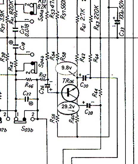
OK ... did some digging ...

- Schematic excerpt
- Board layout from manual
- Actual trace on my machine

Which all seem to follow.

C30+ to R62 and TR06 emitter. Unless I'm going cross eyed here, that matches the actual board markings.

I guess what TRNSFMR is saying is they're ALL wrong?
 

Attachments

  • volume-board-c30-schematic.jpg
    volume-board-c30-schematic.jpg
    46.9 KB · Views: 31
  • volume-board-c30-layout.jpg
    volume-board-c30-layout.jpg
    74.7 KB · Views: 31
  • volume-board-c30-trace.jpg
    volume-board-c30-trace.jpg
    81.8 KB · Views: 37
Last edited:
OK ... did some digging ...

- Schematic excerpt
- Board layout from manual
- Actual trace on my machine

Which all seem to follow.

C30+ to R62 and TR06 emitter. Unless I'm going cross eyed here, that matches the actual board markings.

I guess what TRNSFMR is saying is they're ALL wrong?

I went through my emails with Jim and found this "C30 is in right and wrong on various units. AND the board comes with the solder mask labeled right and wrong."

In mine, the mask was correct, and it was installed correctly. And it seems that way in yours as well.

I'm curious about the caps in your pic of C30, were those the old ones? Or the new ones?
 
So we can trust the schematic anyway. Good to know. I'll mark that board as done ... again.

The pic shows the new Panasonic 1.5uf 50v caps ... tiny little things compared to the originals. I went with Elna Silmic II wherever I could, but some values were just not to be found. Went through two different suppliers to get what I got. The Elna caps can be quite large.

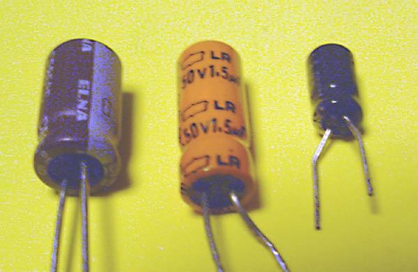
Good example for size comparison ...

volume-board-c30-panasonic.jpg


The Elna on the left is a 1uf 50v - with larger values, it's a good idea to double check the can size before ordering. The one on the right is the new Panasonic 1.5uf 50v. The orange one in the center is the original Panasonic - looks like yours had Elna caps to start with. Must have got a deal on those when yours was built? When did yours leave the factory again? Third digit of your serial number is the year ...

EDIT > > OK, eh ... lookie what I found ...

http://www.audiokarma.org/forums/showthread.php?t=427768

The way I read it is you should get 9.8v at the positive side of C30 if it's installed correctly and X2 power is engaged? I took the liberty of redoing the black blobs on the schematic I posted earlier showing the correct test voltages. I could just make those out on my printout.

volume-board-c30-schematic.jpg


Here's the part that confuses me ...

I had a customer who's unit developed a giant pop when switching to 2X. And then a unit on the bench that we had just recapped, did the same thing. I had to use the scope, pour over the schematics and actually think, to figure it out. Turns out that a cap that feeds the relay that switches to 2X mode has the cap marked backwards on the board. This cap only comes into play in 2X mode, but passes audio to the right channel, and is reverse biased by 8v (installed backwards). It's a 50v cap, and I guess most caps could handle the reverse bias. We just got a new bag of 2.2uf @50v caps in, and I guess they couldn't handle the reverse bias.

2.2uf? Huh? What?? Mine are all 1.5uf ... what are yours? Did I have a brainfart on mine and just assume all six of the caps in that section of the board were all 1.5uf? The schematic unfortunately doesn't list all the values ...
 
Last edited:
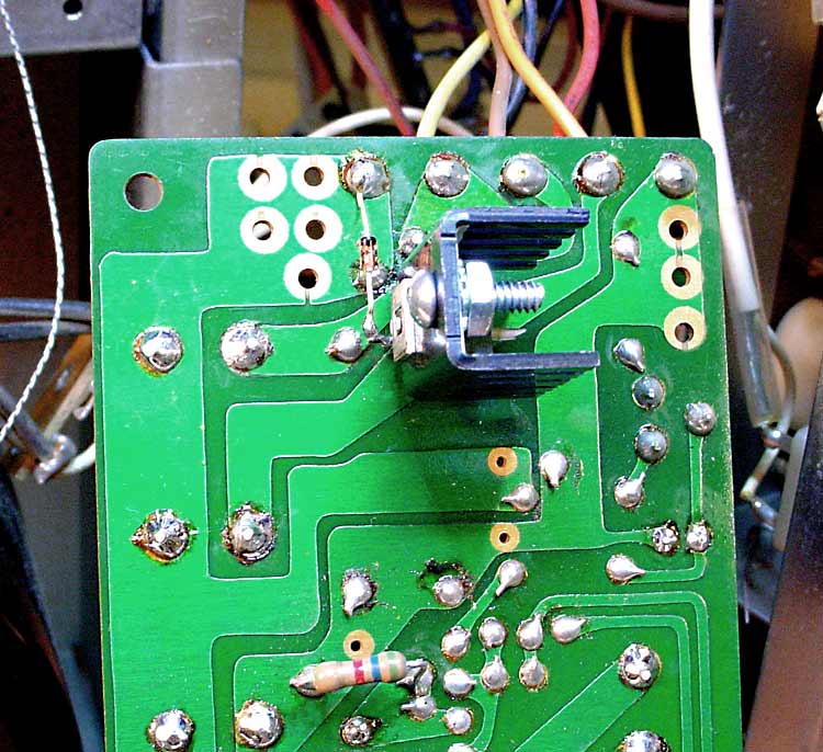
Got sidetracked by good weather, but rain today, so good time to head for the shop ... got the 25v regulator mod done ... and hopefully done right ...

25v-regulator-001.jpg


25v-regulator-007.jpg


Mine turned out a bit different - tucked the regulator in tighter to the board and using a different attachment point for the diode as things got a bit tight. Different heat sink too I think ... I'm sure somebody will head me off at the pass if I made any misteaks ... <G>

PS ... you mentioned setting the pot to 38.9v ... where do you test that?

Anyway ... here's where I'm at so far ...

- F2652 - Dolby sub circuit (done)
- F2633 - Dolby change circuit (done)
- F2634 - 4 Channel board (pinned and done)
- F2689 - Pre-Power Supply (done?)
- Switches cleaned (lot more room to work right now.

Seems to me I should be able to put the front panel back on and still be able to get to the rest of the boards. Anything I overlooked? Once I get that back together, fire it up and see if it still works, then move on ...
 
Last edited:
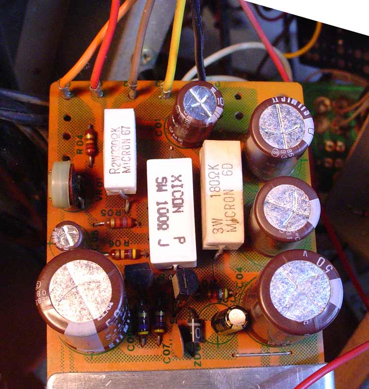
One potential point of confusion for anyone following along ... the LM7824 is a 24 volt package. The 25v regulator mod requires changing out a 180Ω cement resistor for a 100Ω to "fudge" the output ...

25v-regulator-100.jpg


That's the center resistor. Where it gets confusing is the labeling on the original parts. You can see the remaining 180Ω is labeled 180ΩK - not to be confused with a 180KΩ ... I did check the schematic, and it DOES call for 180Ω ... not sure what the labeling is all about - maybe just to keep us on our toes and make sure we're paying attention. :D

EDIT >> Found out the "K" in "180ΩK" denotes ±10% tolerance. The replacement I used has a "J" marking, which makes it ±5%.

One thing I did notice is some heat discoloration on the old parts. I used a 5W replacement for the center resistor - might as well replace the remaining 180Ω with a 5 watter also ... just happen to have one laying about.
 
Last edited:
Back
Top Bottom