Introduction
* As documented in report, ReVox B710 Tape Deck – Successful Wow & Flutter Restoration, section "What did this restoration accomplish? While it took almost 2 years to complete this restoration, partly due to my first experience with a tape deck, my breaking the solenoid plunger (ouch), some delayed parts deliveries, and a random failure in the Reproduce Amplifier board (which I repaired and will document separately), pleased to report my B710 Cassette Tape Deck now looks, operates, and performs like it was new!"
Purpose
* The purpose of this report is to document the troubleshooting and successful repair of an intermittent power-up failure in my B710 MK1 series Reproduce Amplifier PCB.
Failure Description
* This B710 cassette tape deck MK1 serial number 003055, which I purchased new in February 1982 was fitted at factory with the early series Reproduce Amplifier PCB, Layout 1.710.490-12. The circuit diagram published in early service manual section 7/25 displays the date 26.06.81 in the lower left corner (Fig. 1). And indeed, this is the circuit diagram that corresponds to my unit serial number 003055.
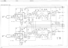
Figure 1. Circuit diagram of MK1 early series Reproduce Amplifier PCB
* Suddenly, one day upon power-up the Left channel would intermittently fail, with symptoms no audio sound or activity on the Peak Reading Meter. The Right channel was fine with both audio sound and Peak Reading Meter operating normally.
* Strangely, the Left channel could sometimes be recovered by touching J1/1, the input of the Right channel - how to explain that?
Troubleshooting
* To facilitate the troubleshooting, I purchased a B710 Distance Card (Fig. 2) which when inserted into the B710 Interconnection PCB enabled accessing both front and back sides of the Reproduce Amplifier PCB. This proved invaluable, without this extension card it would have been extremely difficult to carry out fault finding and troubleshooting.
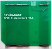
Figure 2. B710 Distance Card - for troubleshooting PCBs in-circuit
* Something was misleading though with labeling in the Reproduce Amplifier circuit diagram, where Right channel J1/1 and J1/2 should have been labelled J1/3 and J1/5. Likewise for Left channel J1/3 and J1/5 should have been labelled J1/1 and J1/2. I'm not complaining as I'm very grateful Studer ReVox made their circuit diagrams available, but it explains why the Left channel could sometimes be recovered by touching the input of the (presumed) Right channel.
* Probing the PCB voltages showed serious imbalances throughout the Left channel. A few examples:
- Capacitor C23 positive terminal, expected ~ +9V. Actual +12.9V.
- Capacitor C7 minus terminal, expected ~ -9V. Actual -1.2V.
- Quad Switch IC2 pin 10, expected ~ +2V. Actual -0.6V.
- Quad Switch IC2 pin 11, expected ~ +2V. Actual -0.7V.
* Carefully inspecting every PCB's solder joint showed nothing untoward.
* Thinking the cause may have been a weak or troublesome transistor, replaced all 4 transistors in the Left channel. NPN transistors Q2, Q3 and Q5 of obsolete BC550C were all replaced with new BC547C. PNP transistor Q4 of obsolete BC560C was replaced with new BC557C. (The "C" designation denotes the higher gain versions). Alas, these transistor changes made no difference, the circuitry was still imbalanced.
* Next, thinking there was a weak or troublesome quad switch IC2 in the Left channel, replaced original MC14066BCP with a new TC4066BP and mounted this IC on new 14-pin DIP socket. As the original MC14066BCP was soldered directly to the PCB, desoldered it carefully using a vacuum desoldering gun set to 300 Deg C. This worked well with no trace delamination or board damage.
* With this refresh of IC2 quad switch the Left channel immediately started working! Feeling elated the fault was now fixed reassembled everything back together, and guess what? The Left channel no longer worked. So, took it apart again and using the extender card the Left channel worked again, put it all back together and the Left channel stopped working. Hmmm.
* Double checking all solder joints once more, and measuring all electrolytic capacitors showed everything in good order.
* Now, just by chance, looking through later version service manual section 7/27 for Reproduce Amplifier PCB "ESE" (labelled with same Layout as before 1.710.490-12), noticed a pair of diodes identified only in handwriting as 1N4448. There is no mention of these diodes in the parts list, nor could I find a reference or documentation what their purpose is or when they were introduced. This does not appear to be an official or released upgrade, although suspect the diode's purpose could have been to clamp voltage swings during powerup. As all applicable factory upgrades were implemented by Studer ReVox when my B710 was sent for repair in 1992, presume the installation of these new diodes came later.
* Armed with this knowledge added a 1N4148 signal diode from my parts supply, cathode to junction of D5/R20 and anode to analog ground. Pleased to report this fixed the Left channel powerup fault, checking with the extender card all in-circuit voltages now measured good!
* However, after putting everything back together the previously working Right channel now failed at powerup, groan.. So, for the Right channel added another 1N4148 signal diode, cathode to junction of D7/R52 and anode to analog ground (Fig. 3). Also refreshed IC4 quad switch with a new TC4066BP and 14-pin DIP socket.

Figure 3. Reproduce Amplifier, Right channel - added diode from D7/R52 to analog ground (left), new TC4066BP on socket (right)
* Finally, by adding these two signal diodes the Left and Right audio channels now power up reliably. I feel confident this has fixed it, as part of the Wow and Flutter investigations the unit was switched on, switched off to cool down, then switched on again multiple times with the Left and Right audio channels powering up reliably every time.
* Figure 4 summarizes what was wrong and what was changed. As part of the initial restoration and circled in Yellow are the tantalum and electrolytic capacitors that were all changed to new, circled in Green are the good components changed but no fault found, and in Red are the critical items that needed to be addressed during troubleshooting.
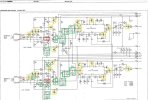
Figure 4. Reproduce Amplifier component investigations - Capacitors (Yellow), No fault found (Green), Critical items (Red).
Final comments
* As mentioned, I'm very grateful that Studer ReVox made all their circuit diagrams available. Without access to and being able to compare both circuit diagrams, early Reproduce Amplifier PCB and later Reproduce Amplifier PCB "ESE", it would have been impossible for me to know what was changed.
References
* ReVox B710 Tape Deck - Successful Wow & Flutter Restoration
* Supplier: revox.name for B710 Distance Card
https://www.revox.name/sell/b710distancePCB/
* ReVox B710 service manuals, both early series and later series
https://www.reeltoreel.nl/studer/Public/Products/Revox/Revox_B710
* As documented in report, ReVox B710 Tape Deck – Successful Wow & Flutter Restoration, section "What did this restoration accomplish? While it took almost 2 years to complete this restoration, partly due to my first experience with a tape deck, my breaking the solenoid plunger (ouch), some delayed parts deliveries, and a random failure in the Reproduce Amplifier board (which I repaired and will document separately), pleased to report my B710 Cassette Tape Deck now looks, operates, and performs like it was new!"
ReVox B710 Tape Deck - Successful Wow & Flutter Restoration
ReVox B710 Tape Deck - Successful Wow & Flutter Restoration
www.audiocircle.com
Purpose
* The purpose of this report is to document the troubleshooting and successful repair of an intermittent power-up failure in my B710 MK1 series Reproduce Amplifier PCB.
Failure Description
* This B710 cassette tape deck MK1 serial number 003055, which I purchased new in February 1982 was fitted at factory with the early series Reproduce Amplifier PCB, Layout 1.710.490-12. The circuit diagram published in early service manual section 7/25 displays the date 26.06.81 in the lower left corner (Fig. 1). And indeed, this is the circuit diagram that corresponds to my unit serial number 003055.
Figure 1. Circuit diagram of MK1 early series Reproduce Amplifier PCB
* Suddenly, one day upon power-up the Left channel would intermittently fail, with symptoms no audio sound or activity on the Peak Reading Meter. The Right channel was fine with both audio sound and Peak Reading Meter operating normally.
* Strangely, the Left channel could sometimes be recovered by touching J1/1, the input of the Right channel - how to explain that?
Troubleshooting
* To facilitate the troubleshooting, I purchased a B710 Distance Card (Fig. 2) which when inserted into the B710 Interconnection PCB enabled accessing both front and back sides of the Reproduce Amplifier PCB. This proved invaluable, without this extension card it would have been extremely difficult to carry out fault finding and troubleshooting.
Figure 2. B710 Distance Card - for troubleshooting PCBs in-circuit
* Something was misleading though with labeling in the Reproduce Amplifier circuit diagram, where Right channel J1/1 and J1/2 should have been labelled J1/3 and J1/5. Likewise for Left channel J1/3 and J1/5 should have been labelled J1/1 and J1/2. I'm not complaining as I'm very grateful Studer ReVox made their circuit diagrams available, but it explains why the Left channel could sometimes be recovered by touching the input of the (presumed) Right channel.
* Probing the PCB voltages showed serious imbalances throughout the Left channel. A few examples:
- Capacitor C23 positive terminal, expected ~ +9V. Actual +12.9V.
- Capacitor C7 minus terminal, expected ~ -9V. Actual -1.2V.
- Quad Switch IC2 pin 10, expected ~ +2V. Actual -0.6V.
- Quad Switch IC2 pin 11, expected ~ +2V. Actual -0.7V.
* Carefully inspecting every PCB's solder joint showed nothing untoward.
* Thinking the cause may have been a weak or troublesome transistor, replaced all 4 transistors in the Left channel. NPN transistors Q2, Q3 and Q5 of obsolete BC550C were all replaced with new BC547C. PNP transistor Q4 of obsolete BC560C was replaced with new BC557C. (The "C" designation denotes the higher gain versions). Alas, these transistor changes made no difference, the circuitry was still imbalanced.
* Next, thinking there was a weak or troublesome quad switch IC2 in the Left channel, replaced original MC14066BCP with a new TC4066BP and mounted this IC on new 14-pin DIP socket. As the original MC14066BCP was soldered directly to the PCB, desoldered it carefully using a vacuum desoldering gun set to 300 Deg C. This worked well with no trace delamination or board damage.
* With this refresh of IC2 quad switch the Left channel immediately started working! Feeling elated the fault was now fixed reassembled everything back together, and guess what? The Left channel no longer worked. So, took it apart again and using the extender card the Left channel worked again, put it all back together and the Left channel stopped working. Hmmm.
* Double checking all solder joints once more, and measuring all electrolytic capacitors showed everything in good order.
* Now, just by chance, looking through later version service manual section 7/27 for Reproduce Amplifier PCB "ESE" (labelled with same Layout as before 1.710.490-12), noticed a pair of diodes identified only in handwriting as 1N4448. There is no mention of these diodes in the parts list, nor could I find a reference or documentation what their purpose is or when they were introduced. This does not appear to be an official or released upgrade, although suspect the diode's purpose could have been to clamp voltage swings during powerup. As all applicable factory upgrades were implemented by Studer ReVox when my B710 was sent for repair in 1992, presume the installation of these new diodes came later.
* Armed with this knowledge added a 1N4148 signal diode from my parts supply, cathode to junction of D5/R20 and anode to analog ground. Pleased to report this fixed the Left channel powerup fault, checking with the extender card all in-circuit voltages now measured good!
* However, after putting everything back together the previously working Right channel now failed at powerup, groan.. So, for the Right channel added another 1N4148 signal diode, cathode to junction of D7/R52 and anode to analog ground (Fig. 3). Also refreshed IC4 quad switch with a new TC4066BP and 14-pin DIP socket.
Figure 3. Reproduce Amplifier, Right channel - added diode from D7/R52 to analog ground (left), new TC4066BP on socket (right)
* Finally, by adding these two signal diodes the Left and Right audio channels now power up reliably. I feel confident this has fixed it, as part of the Wow and Flutter investigations the unit was switched on, switched off to cool down, then switched on again multiple times with the Left and Right audio channels powering up reliably every time.
* Figure 4 summarizes what was wrong and what was changed. As part of the initial restoration and circled in Yellow are the tantalum and electrolytic capacitors that were all changed to new, circled in Green are the good components changed but no fault found, and in Red are the critical items that needed to be addressed during troubleshooting.
Figure 4. Reproduce Amplifier component investigations - Capacitors (Yellow), No fault found (Green), Critical items (Red).
Final comments
* As mentioned, I'm very grateful that Studer ReVox made all their circuit diagrams available. Without access to and being able to compare both circuit diagrams, early Reproduce Amplifier PCB and later Reproduce Amplifier PCB "ESE", it would have been impossible for me to know what was changed.
References
* ReVox B710 Tape Deck - Successful Wow & Flutter Restoration
ReVox B710 Tape Deck - Successful Wow & Flutter Restoration
ReVox B710 Tape Deck - Successful Wow & Flutter Restoration
www.audiocircle.com
https://www.revox.name/sell/b710distancePCB/
* ReVox B710 service manuals, both early series and later series
https://www.reeltoreel.nl/studer/Public/Products/Revox/Revox_B710