
• The move to the new server is done. There are some software and database maintenance updates in process. This has us passing the hat around to help out. We appreciate any donations. Seriously, even a dollar helps. The payment page may be found here - https://www.audiokarma.org/support.html

Rewiring An Astatic G Stand With A 3 Pin Connector

ookpik

New Member
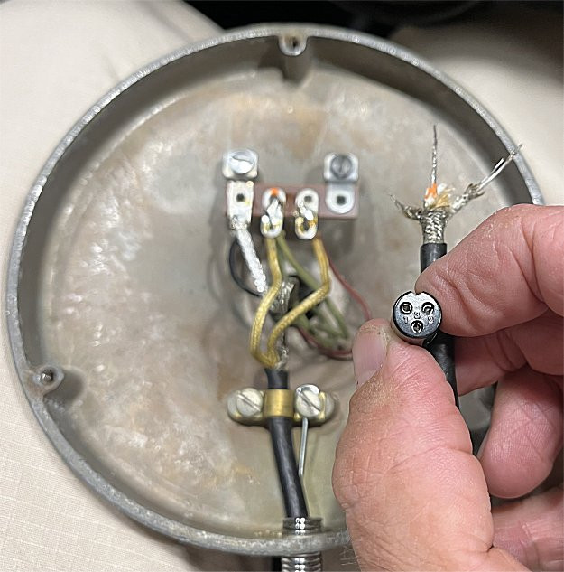
I have an 3 pin Astatic G stand that I wish to add a 3 pin female connector to the end of the cord.

The cord has two white wire conductors with shield.

Which wires do I solder to pins 1 - 2 - 3 on the connector shown?

White wire with orange terminal dot to pin number ?

White plain wire to pin number ?

Shield wire to pin number ?

Any help in this matter would be greatly appreciated!
:)


Please see the photo below for additional info.
base1.jpg
 
Register to hide this ad
ooh, a G stand. I have one of these on an old Tram CB.

Where the wire goes depends what it plugs into. That looks suspiciously like a CB plug. Not too many ran a 3 pin connector but I'm not calling to mind what did. Every manufacturer seemed to use their own wiring arrangement anyway.

anyway, the 3 wires are ground, shielded audio, and the other is switched to ground when you squeeze the bar on the side. In a transmitter thats what pulls the relay to make it do it's thing but in a PA application it probably runs a muting relay. You'd have to ohm check the thing to know which color is what. Lock the bar with the sliding hook thing if its still there and see which wire has only a handful of ohms to the shield. The mic element will typically read open circuit, but it may ground when un-keyed. Been a while since I was into one of these and I don't remember that detail.
 
Just saw this, so I'm late for the game. Op: you'll need to know how your intended equipment is connected internally. Many d104 mics were amplified & were a desired accessory for about any transceiver, whether cb or ham, & were usually supplied minus a plug. The understanding was that the factory had no clue what it was going to be used with, so one had to d i y. I have a wiring diagram for almost every d104 version made, which enabled one to work it out themselves. The most common 3 wire connector was the standard 1/4" trs ( tip/ ring/ sleeve) plug, as used on headphones, guitars, etc.
 
Back
Top Bottom