• The move to the new server is done. There are some software and database maintenance updates in process. This has us passing the hat around to help out. We appreciate any donations. Seriously, even a dollar helps. The payment page may be found here - https://www.audiokarma.org/support.html

Rh84 built, first impressions

I guess what I should have said was that with the certain caps it may be passible without bypassing, at least to me. I've used some motor run polyprop in oil caps before and they were nice sounding, but yes closer to perfection I could see multiple bypass caps for impedance of diff frequencies. Someday I'll have a whole audio system that is a work of art. Do you use full range speakers without crossover caps?

Jake,

You asked .... Do you use full range speakers without crossover caps?[


I have owned fullrange in the past, but they aren't, and so I evolved to KISS two-way systems. Use ALTEC 515B and 802D drivers 825 VOTT enclosures, crossed over at 800 hZ. ( aka A7-8 )


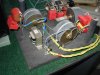
P1010017.JPG
a VOTT Simple 12dB crossover, Butterworth, no EQs. SEE multiple bypassing. The large gray round industrial film caps do about 1.500 A. instantaneous. The ALTEC drivers respond to them nicely.

Dowto1000
 
Last edited:
I have owned fullrange in the past, but they aren't, and so I evolved to KISS two-way systems. Use ALTEC 515B and 802D drivers
825 VOTT enclosures, crossed over at 800 hZ. ( aka A7-8 )


View attachment 1214758 in a VOTT ( 825) enclosure, crossed over at 800 hZ. Simple 12dB crossover, Butterworth, no EQs. SEE multiple bypassing below.

Dowto1000
That's right, you've posted those but wasn't sure if used any full range as well. What does KISS stand for, new term to me. You should really make a youtube video of your system, I know youtube will degrade and compress but would still be cool and I've personally been able to get some kind of an idea how certain gear sounds that way.
 
Actually this the same rh84 circuit that you are tweaking. I built this one maybe 5 years ago? My take was to use 6v6 instead and i subbed a 6sl7 for the 12at7. I borrowed from the rh universal circuit for the front end. I was testing some 5992 for a buddy. The 5992 have a cool purple glow when working. Found this photo that looks similar to mine.
<DIV align=center>
<img src="http://usr.audioasylum.com/images/5/56663/dsc05665.jpg">
</DIV>
 
They seem fair priced so I'll give them a shot, thanks. Is that a new amp you've built in your pic?
They are actually an old computer tube, so probably thousands of them floating out there. Actually, there are many 'computer' tubes that are of medium high gain like the at7 but built to withstand the long shut off conditions that computer tubes are experiencing. Some are very good sounding tubes. They are also Euro versions of the tubes like the 7062 , but in the rh amp it was just ok. Perhaps i did not give it enough time in circuit?
 
They are actually an old computer tube, so probably thousands of them floating out there. Actually, there are many 'computer' tubes that are of medium high gain like the at7 but built to withstand the long shut off conditions that computer tubes are experiencing. Some are very good sounding tubes. They are also Euro versions of the tubes like the 7062 , but in the rh amp it was just ok. Perhaps i did not give it enough time in circuit?
For the RCA's that you liked were they black plates or not? Were they the triple mica? Computer tubes would be great for an integrated amp if you didn't want high voltage on a phono stage or something when not in use.
 
I'm pretty busy tis week but Friday I'm going to take more measurements and try bypassing and maybe try messing with that input pot as well, although I do see a 100k pot on a lot of diy tube amps so I wonder why it wouldn't be ok in this one. The bass is slightly better now after a couple more hours but still slightly harsh mids and that at least on the Klipsch. If I end up liking this amp I may build one with a preamp stage next time. I'm also going to build some speakers soon once they settle and tweak it to fit the amp perfect. Just recently got one of those circle jigs so going to have some fun with my router.
 
I'm pretty busy tis week but Friday I'm going to take more measurements and try bypassing and maybe try messing with that input pot as well, although I do see a 100k pot on a lot of diy tube amps so I wonder why it wouldn't be ok in this one. .
Well, if you are going to use a pot you would have to use at least a 500k to 1Meg value. The input grid to ground resistor helps to set the gain of the tube and also the input impedance which is very important. I have not memorized the exact technical reasons why the grid to ground resistance relates to the other tube parameters but keeping all of them in their proper values makes for lowest distortion.
 
It is something unclear to me because plenty of people use 100k but I have also seen some older amps with 1 meg. Ive mostly thought as long as the amps input z was 10 times the device driving it you should be good to go. What I'm starting to think is maybe the amp is pretty balanced and I'm just used to a bit more bass and thicker mid bass. It also comes down to my sources not having enough guts to drive it full. Curious though about what your screen voltage and plate voltage was because my plate and screen ended up both at 280 volts. And plate dissipation is a little bit over 11 watts. I'm using a more the rugged 6p14pev tubes.
 
I don’t want to hijack, but I’m interested in DC. Are there any risks involved? What precautions (circuit mods) must be taken to remove the coupling cap?
 
I don’t want to hijack, but I’m interested in DC. Are there any risks involved? What precautions (circuit mods) must be taken to remove the coupling cap?
I'm new to DC as well, basically you need to balance the circuit and maintain that balance by using good resistors, carbon comps would be bad with drift. I know with solid state DC you should always have a relay circuit to protect from DC hitting the speakers since you have no output cap. But since output transformer block DC I'm not sure that's necessary.
 
Btw update on the burn in, about 7 hours in now and things are looking up, still haven't changed the input impedance yet or bypassed filter caps but man jazz is starting to sound better than any of my other amps and soundstage has improved a bit as well, very black background with good instrument separation and very vocals are more centered now. It's now becoming enjoyable, still a bit forward and I want a bit more bass but it's actually sounding closer to a McIntosh in a way, it's so clean and clear with a touch of warmth, lacks the power of a Mac but instrument separation sounds similar. I'm thinking about building myself one of these now if this keeps up.
 
[/ATTACH] 2 of 2 REV USE.JPG
I don’t want to hijack, but I’m interested in DC. Are there any risks involved? What precautions (circuit mods) must be taken to remove the coupling cap?

Hey !!!! You are in KCMO and I am in Warrensburg, MO, just 55 miles away. !!!


Good for you. Its virtually impossible to out-perform a two stage direct coupled amp. Getting rid of the coupling cap is the BEST thing a person could do, if you seek high audio playback performance.

To DC an amp, the second stage must be elevated, typically by using about a 20 Watt ( usually higher ) power resistor, as a Rk or cathode resistor ( self bias here ) of the second stage. ( R6 above. )

In a DC amp, the plate voltage of the first tube, becomes the grid ( biasing voltage ) of the Finals tube.

This means you usually have an overall B+ that is higher, to feed the second "elevated voltaged " ( Finals ) stage. A typical cap-coupled 2A3 amp may employ a B+ of about 300 - 320 VDC, whereas a DC 2A3 amp will have a total B+ of 450 to 480 VDC.

Let me give you some numbers, you can refer to the highlighted schematic above.

Assume 150 VDC on the plate of the first tube, and hence, due to the direct couple, on the GRID of the Finals tube, a 2A3. Lets say you want to conservatively run 42 mA. at 250 VDC Plate to Cathode across the 2A3's plate, ( which is a great OP Point BTW ) !!

Lets say it takes - 50 VDC of grid bias, ( from the 2A3 tube's characteristic curve graphs ) at 42 mA and 250 P-K.

OK, this means the Final's cathode needs to be 50 VDC higher than the grid, or at 200 VDC . This calls for a 4,761 Ohm Rk resistor value ( 200 V divided by 0.042 A , Ohms Law ). The plate of the 2A3, at 250 VDC P- K, needs to be at 200 V + 250 VDC or 450 VDC, on the plate. There will be an R times I loss, across the primary of the SE output transformer, to account for. Lets say the output transformer has a 100 Ohm Primary winding , so it loses 4.2 VDC ( 100 Ohms times 0.042A. )

This means your "overall" amplifier B+, to the Final tubes, has to be 454.2 VDC, to have it all balance out perfectly. ( 200 V on the Rk, 250 VDC across the plate, and 4.2 VDC more to account for R times I losses across the Output transformer's primary winding.

It best to use a tube rectifier in a DC amp, I like 5U4GBs, and a current inrush limiter ( called a Thermistor, a CL-90 ) after the fuse, on the Primary side of the Power Transformer. This provides a gentler start up, and long term reliability, reduces turn-on circuit stressing.

I have already written a comprehensive multi-page article on how to design and implement such circuits, Contact me privately at my email address, and I will email it to you, or anyone else who is interested. I HIGHLY recommend a two stage DC amp, with a high mu ( typically 100 ) Driver tube.

You travel on the "right track" with two stage Direct Coupled SE amps. IME, a coupling cap is sonically POISON, compared to a Direct Couple.

Dowto1000

 
Last edited:
Btw update on the burn in, about 7 hours in now and things are looking up, still haven't changed the input impedance yet or bypassed filter caps but man jazz is starting to sound better than any of my other amps and soundstage has improved a bit as well, very black background with good instrument separation and very vocals are more centered now. It's now becoming enjoyable, still a bit forward and I want a bit more bass but it's actually sounding closer to a McIntosh in a way, it's so clean and clear with a touch of warmth, lacks the power of a Mac but instrument separation sounds similar. I'm thinking about building myself one of these now if this keeps up.


Jake,

Your amps are not supposed to sound NOT like another amp, ( Mac, etc ), but rather. like the real thing, sound like music !!

All you are likely hearing is the differences between a two stage SE amp and a three stage SE amp. A two stage can be better, less circuitry to degrade the signal.

Next, lets simplify the circuit..... by changing the RH 84 amp's topology. Ditch it's coupling cap !!! You will thank me. A coupling cap is to be avoided IMO, best left out !! Use a KISS direct couple between the two tube stages

Dowto1000
 
Last edited:
It is something unclear to me because plenty of people use 100k but I have also seen some older amps with 1 meg. Ive mostly thought as long as the amps input z was 10 times the device driving it you should be good to go. What I'm starting to think is maybe the amp is pretty balanced and I'm just used to a bit more bass and thicker mid bass. It also comes down to my sources not having enough guts to drive it full. Curious though about what your screen voltage and plate voltage was because my plate and screen ended up both at 280 volts. And plate dissipation is a little bit over 11 watts. I'm using a more the rugged 6p14pev tubes.
I would be wary of going over the 250v G2 voltage maximum. 250v is also the limit for the 6p14p-eb tubes. How did you set the G2 voltage? was it via a resistor or did you use a zener or even a choke? It would be best to stay around the 5% limit of variation in voltages and you are over 10%. While your amp will be ok, the tube life will suffer and there maybe a possibility of the power tube going over current and taking out the output trans too.
 
I'm new to DC as well, basically you need to balance the circuit and maintain that balance by using good resistors, carbon comps would be bad with drift. I know with solid state DC you should always have a relay circuit to protect from DC hitting the speakers since you have no output cap. But since output transformer block DC I'm not sure that's necessary.


Right Jake, with DC tube amps, NO relays needed, or ever wanted. Less is more.

Dowto1000
 
I would be wary of going over the 250v G2 voltage maximum. 250v is also the limit for the 6p14p-eb tubes. How did you set the G2 voltage? was it via a resistor or did you use a zener or even a choke? It would be best to stay around the 5% limit of variation in voltages and you are over 10%. While your amp will be ok, the tube life will suffer and there maybe a possibility of the power tube going over current and taking out the output trans too.
I used a 2.2k for each channel as shown on the schematic. That was measured from ground though so wouldn't it be about 10-13 volts less to the cathode then? I figured it would be ok with that type of tube because plenty of people triode strap el84 tubes around that voltage anyways, more curious if you got the same results on one of your version 1 rh84 amps? I should see what it reads in ul mode.
 
Jake,

Your amps are not supposed to sound NOT like another amp, ( Mac, etc ), but rather. like the real thing, sound like music !!

All you are likely hearing is the differences between a two stage SE amp and a three stage SE amp. A two stage can be better, less circuitry to degrade the signal.

Next, lets simplify the circuit..... by changing the RH 84 amp's topology. Ditch it's coupling cap !!! You will thank me. A coupling cap is to be avoided IMO, best left out !! Use a KISS direct couple between the two tube stages

Dowto1000
A dc version of the RH would be interesting, sounds like a fun build.
 
Back
Top Bottom