• The move to the new server is done. There are some software and database maintenance updates in process. This has us passing the hat around to help out. We appreciate any donations. Seriously, even a dollar helps. The payment page may be found here - https://www.audiokarma.org/support.html

SA-7500 2SC1451 Replacement Question (KSC3503DSTU)

Segasonic91

Active Member
I got around to starting on recapping my SA-7500 yesterday. I also replaced the faulty 2SC1451 transistors. I only capped the two tone boards and the two teansistors so far. I discovered that I did not have the bi-polar caps I thought already arrived so I decided to put it back together until I have everything.

I tested it tonight but the relay was not kicking in. I am guessing it is the 2SC1451 transistors I installed. They are new NEC models which I thought would be fine as it is like for like. I installed with the little lip on the transistor facing "up", the direction of the arrow on the board.

I discovered that I did actually buy 2 KSC3503DSTU transistors which I will install tomorrow. I am just wondering how they are installed? They are marked as bi-polar so does it matter which way they go in? Should the numbers on the plastic be facing towards the front of the amp?

Thanks!
 
Register to hide this ad
What about the installation for the KSC3503DSTU? Which leg goes where? Sorry for the noob questions, it is the first time I have done something like this which is more than just simple caps.

EDIT: I just found something that may guide me to installing the other transistors.

It says the 1451 is "ebc" and the 3503 is "ecb". So I am guessing the legs being 1, 2 and 3 corresponds to the ecb note just as the 1451's pins 1, 2 and are "ebc" as the above link shows. I am assuming the leg numbers of the 3503 is with the numbers on the plastic facing forward.
 
Last edited:
Get yourself a cheapie component tester from Amazon or eBay, before installing any new replacement, you can verify the pinouts. Handy tools for about 10 bucks.
 
I am assuming the leg numbers of the 3503 is with the numbers on the plastic facing forward.
Yes
 
Get yourself a cheapie component tester from Amazon or eBay, before installing any new replacement, you can verify the pinouts. Handy tools for about 10 bucks.

Yes, I really need to get one. I lost my old one when I moved.

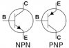
So here is an incredibly noob question, what do the "e,c,b" letters stand for? Will that show on the tester?
 
Welcome to Audiokarma!

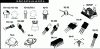
transistor_images.png

Some different types of transistor cases:

ENCAPSULADOS Transistores.GIF

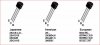
Transistor legs. Note this is informative and general, consult datasheet for specific transistor:

Capture15.JPG
 
Last edited:
Thank you so much to everyone for the help!

I feel like I am getting somewhere now! I just wish it was easy to seperate leads from boards like the AU-9900. I have kept the leads attached to the boards and worked around them that way. If I could easily seperate each board from the amp it would be so much damned simpler! I just don't fancy disconnecting all those wires that are wrapped around each post. I guess I will just have to if I ever want to get it 100% re-capped.

I have replacements for tye A725 and 1313 transistors but have not installed them yet. Is it advisable to replace resistors as well or are they fine to keep as is?

Thanks!
 
Last edited:
Well, it's always good practice to measure each resistor,(with one leg disconnected to eliminate in-circuit conditions that could skew a reading) for correct functioning
- some of those problematic transistors could take a resistor with them. It's far more fun to find them quickly like that than after the sinking feeling when something isn't behaving.

The advice isn't just for the beginners, this is routine for even "experts".

I approach a circuit with the attitude: "PROVE to me you are capable of doing your function"...
 
Well, it's always good practice to measure each resistor,(with one leg disconnected to eliminate in-circuit conditions that could skew a reading) for correct functioning
- some of those problematic transistors could take a resistor with them. It's far more fun to find them quickly like that than after the sinking feeling when something isn't behaving.

The advice isn't just for the beginners, this is routine for even "experts".

I approach a circuit with the attitude: "PROVE to me you are capable of doing your function"...

Very good advice! If I could easily get every board out, I would change everything. The age of this thing, it is way past expected spec life, I would love to have it working and soumding exactly as it did in 1976. The sound was okay, but not great.

The annoying thing about all of this is that I paid $265 to get the thing fixed! I even TOLD them what the problem was and what needed to be replaced! 1 day after getting it back, I started getting the horrible "feedback" sound in the right channel again! Due to circumstances at the time, I was unable to return it.

Looking at the inside, I cannot see a single solitary transistor that was replaced, so I don't think they did ANYTHING to it! I will be very happy once I have a proper work table set up so I can fully concentrate on one thing at a time. I am dying to start the AU-9900 recap, but need to wait until I have a proper workspace. After watching a 4 part recap video on youtube, I am not "scared" of that big complicated looking machine. It is much easier than I thought and at least the boards have PROPER cable connections that can easily be unhooked! Unlike the Pioneer.

I would love to get my hands on a cheap SA-9800 or there abouts from Japan and fully restore it. Guess I have to wait for Japan Post to start up again!
 
UPDATE: Okay, I installed the other transistors as they should be and after finally getting the legs through the holes to solder them, I got a click!

I re-connected the speakers and turntable to test and just my luck, I slipped as I was plugging in the right plug and the damn thing broke off inside! I tried the left plug in phono 2 and all I get is a feedback sound. Does that mean the legs are not in correctly?

I have not checked the bias or anything yet, I need a new multimetre which I hope to have on the weekend. Could a transistor not be working and causing the feedback sound? As I said before, I have replacements but have not installed yet.
 
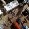
Here is a photo of the install. Left to right I have E, C and B. Far left is obviously E, at least I am certain that is correct. Middle is C and last on the far right is B.

15913555710453633499412360328490.jpg
 
Back
Top Bottom