• The move to the new server is done. There are some software and database maintenance updates in process. This has us passing the hat around to help out. We appreciate any donations. Seriously, even a dollar helps. The payment page may be found here - https://www.audiokarma.org/support.html

SA-7500 relay and other problems

SMD88

Active Member
Hi guys,

Long time lurker/reader, finally made an account!

I have a SA-7500 that I got from a friend at work for free as it has problems. The unit was re-capped and had all transistors and power drivers replaced. However, afterwards it would no longer click out of protection.

I have been going through the amp removing components and reinstalling to make sure they are in correctly. I have done half of the protection board and it seemed to start making progress. When I checked the amp after removing/re-installing the transistors on the right side (split as per the service manual if that makes sense, opposite side to the relay), the relay seemed to click. Although it was a weak click and happens almost instantly.

Upon plugging a turntable and some speakers in, the speakers were hit with a nasty noise once the relay made its feeble click noise. The relay is brand new as well.

Tried adjusting bias but the potentiometers do not make the DMM move at all. I know if should be on for 10 minutes, but I do not want to do that until I know it is safe to do so.

I only have one pair of pots left over from a SA-9800 rebuild, so they are the originals. I am planning to remove and install the last couple of transistors on the relay side of the protection board tomorrow in hopes it will fix the problem. Any ideas about where this issue is stemming from? The instant relay kick and nasty noise being emmited... what could this be caused from? I love the SA-7500, and would like it to be completed before I tackle two SA-9500s and a SA-9500 II.

Thanks in advance! :D
 
Register to hide this ad
Welcome aboard.

I have a SA-7500 that I got from a friend at work for free as it has problems.
Should have fixed the " problems " before recapping.

If this nasty noise is in both channels.. Start with the power supply. Verify all parts are properly installed , No solder bridging on the solder side of the board. No lifted solder pads or traces.
Although it was a weak click and happens almost instantly.
Relay driver transistor maybe shorted.
 
Just thought I would share my experience with a similar issue.

I had one on my bench that came in with a protection issue. The amp would not click out of protection when powered on. The unit did come out of protection once I set the junction point and idle current as per the revised instructions on page17 and 18 of the service manual found on hifiengine.

While listening and evaluating on the bench afterward, the unit did click in/out of protection a few times. Turns out the old trimmers were flaky and susceptible to vibration. The problem was completely resolved once I replaced the trimmers with Bourns multiturn trimmers. It’s been great for about a week of use, now I’m recapping it.

Just in case you don’t have the service manual correction, see the following note.

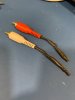
Note: This amp has a somewhat unorthodox method for adjustment. You need to remove the preamp/poweramp jumper and add RCA plugs with 5.1K resistors across each channel input of the power amp.
 
Last edited:
Welcome aboard.


Should have fixed the " problems " before recapping.

If this nasty noise is in both channels.. Start with the power supply. Verify all parts are properly installed , No solder bridging on the solder side of the board. No lifted solder pads or traces.

Relay driver transistor maybe shorted.

The unit had already been capped and had transistors etc changed before I got it, I think that is what started the problems. They did use Panasonic FCs, so the parts are all good. I added some wima films for the under 10uf caps. Thanks for tye advice though, will go over those last few transistors on the relay board to see if it helps the relay issue.
 
Just thought I would share my experience with a similar issue.

I had one on my bench that came in with a protection issue. The amp would not click out of protection when powered on. The unit did come out of protection once I set the junction point and idle current as per the revised instructions on page17 and 18 of the service manual found on hifiengine.

While listening and evaluating on the bench afterward, the unit did click in/out of protection a few times. Turns out the old trimmers were flaky and susceptible to vibration. The problem was completely resolved once I replaced the trimmers with Bourns multiturn trimmers. It’s been great for about a week of use, now I’m recapping it.

Just in case you don’t have the service manual correction, see the following note.

Note: This amp has a somewhat unorthodox method for adjustment. You need to remove the preamp/poweramp jumper and RCA plugs with 5.1K resistors across each channel input of the power amp.


Thanks! Hmmm, I did not add those 5.1k resistors to the power amp section. The jumpers are AWOL actually. I thought it was a step that could be skipped, silly me! Is that why the trimmers are not doing anything? I plan to replace the old trimmers as soon as I can, but only have one set at the moment and mouser is out of stock for one of the two.
 
The resisitors are required for the adjustments to be correct. I made my own rca plugs with 5.1k resistors to use for the procedure.
5DE3F529-A3DF-42BD-B5C5-7730B5459D3B.jpeg

The preamp/poweramp jumpers are easy to make with 8 gauge wire.
 

Attachments

  • 8208E1BE-7F2B-4CB1-AC8B-849A910DD75E.jpeg
    8208E1BE-7F2B-4CB1-AC8B-849A910DD75E.jpeg
    71.8 KB · Views: 23
If you do not have the 5.1kΩ resistor you can just pull the jumpers. If you do not have jumpers you can use short RCA male to male cables when you are ready to pass signal again. The 5.1k resistor plugs do help reduce possible noise coming in on the power amp inputs.
Thanks! Hmmm, I did not add those 5.1k resistors to the power amp section. The jumpers are AWOL actually. I thought it was a step that could be skipped, silly me! Is that why the trimmers are not doing anything? I plan to replace the old trimmers as soon as I can, but only have one set at the moment and mouser is out of stock for one of the two.
FWIW, replacing the trimmers is a good idea.
If the relay is not pulling in you cannot measure dc offset at the speaker connections, because the relay is open. You can measure it on the power amp (AWH-040) output pins 3 and 17.
 
The resisitors are required for the adjustments to be correct. I made my own rca plugs with 5.1k resistors to use for the procedure.
View attachment 2280510

The preamp/poweramp jumpers are easy to make with 8 gauge wire.

Those look great. So, just attach each to the positive/negative and heat shrink? Sounds nice and easy :D

I have just finished working on the amp, pretty sure all transistors have been re-installed now. One problem is that I forgot to take a photo of the power amp board, where the yellow wire is attached to a .47uf cap. I upgraded it to a 1uf wima, 1uf is listed in the service manual which I assume was a later revision.

I attached the wire back to the 1uf, looking from the foil side, it is the right leg. Just want to make sure this is correct. I remember it being on a double pad, which this one is.
 
I would recommend to replace the .47 with the same value low noise cap. The 1uF will affect the high frequency and make the amp too bass-y. I know because I tried it when I didn’t have any .47uF in hand. I ended up ordering when I found the sound degraded.

My poweramp board is AWH-040A. Looks like this model had several revisions that were not reflected in the schematics available online.
 
I would recommend to replace the .47 with the same value low noise cap. The 1uF will affect the high frequency and make the amp too bass-y. I know because I tried it when I didn’t have any .47uF in hand. I ended up ordering when I found the sound degraded.

My poweramp board is AWH-040A. Looks like this model had several revisions that were not reflected in the schematics available online.
Ahhh! Thanks for letting me know! I will get some .47uf and replace them.
 
Referrencing this thread; [https://audiokarma.org/forums/index...-notes-and-some-modifications-longish.842556/], I changed the 100uf 16v cap on the control board to a 220uf 16v.

Did a few more solder touch ups on the boards and when I checked the amp, the relay clicked. The first time I powered it, the relay clicked fairly loudly and not instantly. Second time, it seemed a bit weaker, but was taking the "normal" 4-5 seconds to click in. I have not tested it with speakers as yet. I have some old speakers from old beloved SONY stereo circa 2002, that I am going to use to test. Do not want to damage my good speakers.
 
Checked the amp tonight and still a loud HUM on both channels. It almost sounds like a weird ground, or lack of, HUMMMM. The power outputs were changed, could it be a problem there? Is there anything else I should look at?

I did find a loose wire from a wire wrap, could that have something to do with it? I found another wire wrap that looked like it was missing a wire, but no wire to be found. What it the best way to get photos up on this site? I figure photos will make this easier!!
 
You can copy and paste a picture into your post, or click on the "Upload a File" button, then browse to file folder it is in, select and upload it.

Where does the other end of the loose wire connect?

What pin on what board has a wrap without a wire connected?
 
Checked the amp tonight and still a loud HUM on both channels. It almost sounds like a weird ground, or lack of, HUMMMM. The power outputs were changed, could it be a problem there? Is there anything else I should look at?

I did find a loose wire from a wire wrap, could that have something to do with it? I found another wire wrap that looked like it was missing a wire, but no wire to be found. What it the best way to get photos up on this site? I figure photos will make this easier!!

I have some pics of where the wires are connected on my working SA-7500. LMK if you need them.

Also, the phono section on this amp easily picks up environmental noise if you have the cover off. The cover shields it completely. If your hum goes away on Aux or Tuner but is there on Phono, try putting the cover on.
 
I have some pics of where the wires are connected on my working SA-7500. LMK if you need them.

Also, the phono section on this amp easily picks up environmental noise if you have the cover off. The cover shields it completely. If your hum goes away on Aux or Tuner but is there on Phono, try putting the cover on.

That would be fantastic, thank you. I do have the cover on, actually and tried AUX this time as it was quicker. I did notice a screw missing from one of the output transistors, was not sure if this would cause some sort of feedback or grounding issue those. They are a bitch to get to, so have not tried to put a screw in yet.

Could they cause an issue if they are not set properly? Or would there just be no sound and/or relay click? Had a problem on a 9500 I am fixing blowing a fuse because of bad outputs, so I am always cautious about output problems.

You can copy and paste a picture into your post, or click on the "Upload a File" button, then browse to file folder it is in, select and upload it.

Where does the other end of the loose wire connect?

What pin on what board has a wrap without a wire connected?

Thanks! I will do that.

I will check again to see which pin it is, from memory, I think it was on the power amp board.
 
A screw missing from an output transistor mounted on a heatsink may greatly reduce the thermal transfer from the transistor to the heatsink, causing the transistor to overheat. It should not be operated without being properly mounted. To me that indicates sloppy work by a previous attempt at repair.
The collector connection to the socket is through the screws as well.
 
@SMD88 , I hope this helps.
Below are some pictures I took before working on the equalizer and switch circuit boards. I try to take pictures before moving any wire-wrapped boards. It saves time if one or two come loose.


29FD4129-1017-42B3-9061-16C196E4CC92.jpeg
7F87084A-C74D-48B8-BD40-667EE03BD0B5.jpeg
77372AD5-8F82-4736-B7B9-29D393091A03.jpeg
6D8EFB58-5611-4911-A3D8-76CE27BB0A73.jpeg
8F65242D-B9A6-4D68-AF29-387E97382955.jpeg
 
Last edited:
Thank you very much for that, much appreciated! I have not looked at the SA-7500 again as yet, as I have been trying to fix an SA-9500. Will have a look today though, once I am done with the its big, musclebear brother.
 
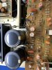
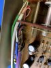
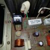
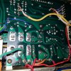
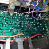
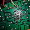
Finally got around to taking some photos. Discovered that one of the big transistors on the power amp has snapped the middle leg. I am pretty sure I have a couple of those still, so will change it on the weekend.

I may have to steal KSA1845 transistors out of the 7500 though. It seems that I have "lost" the stash I had of them. I bought 25 or 30 at a time everytime I ordered caps just to stock up as they were cheap and I thought it would be good to have plenty of them. Well, that was a very good idea seeing as they out of stock everywhere. Too bad I cannot FIND them now! Grrr!! I wanted to start work on my second 9500 as the caps arrived from mouser today. As it is, I will have to steal the two 25 turn potentiometres as THEY are also out of stock! So even if I finally get the 7500 working by replacing that transistor (I will probably replace all 4), it will be up and running for a few months because of part shortage.

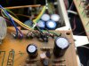
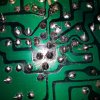
If possible, I would like confirmation that the yellow wire in the 4th photo, attached to a cap leg, is correct please. There also a couple of points that looked joined, and I am not sure if they should be. The solder keeps flowing into the points, but it is hard to make out if they are solder points that SHOULD be joined or not.

EDIT: Whoops! Kept thinking I replaced the turn pots on this but I haven't. Damn this parts and cap shortage! Is there anything that can be used in place of the 1845's?
 

Attachments

  • 20210726_234056.jpg
    20210726_234056.jpg
    192.1 KB · Views: 17
  • 20210726_233824.jpg
    20210726_233824.jpg
    201.4 KB · Views: 16
  • 20210726_233816.jpg
    20210726_233816.jpg
    201.4 KB · Views: 17
  • 20210726_234005.jpg
    20210726_234005.jpg
    211 KB · Views: 16
  • 20210726_233953.jpg
    20210726_233953.jpg
    199.7 KB · Views: 16
  • 20210726_234019.jpg
    20210726_234019.jpg
    167.1 KB · Views: 16
Back
Top Bottom