• The move to the new server is done. There are some software and database maintenance updates in process. This has us passing the hat around to help out. We appreciate any donations. Seriously, even a dollar helps. The payment page may be found here - https://www.audiokarma.org/support.html

SA-7800 - relay won't click.

Thanks for the replied backlight and mark.

Backlight, do you have a list of the electrolytics? I'm gonna be doing that too eventually, if I get it working.

Mark, that makes sense on a level of general understanding but I need to look at the manual to see if I think I could manage it. Right now I'm not entirely sure I could, but I'll investigate over the weekend.
 
Thanks for the replied backlight and mark.

Backlight, do you have a list of the electrolytics? I'm gonna be doing that too eventually, if I get it working.

Mark, that makes sense on a level of general understanding but I need to look at the manual to see if I think I could manage it. Right now I'm not entirely sure I could, but I'll investigate over the weekend.


I've worked on a few, when you're going to go further than the repair, let me know and I'll get the parts numbers. I also did the main caps on one, they were half as tall, and I had to drill the board to fit the lead spacings.

You will want to beef up the heatsinks on the power transistors for the power supply. and they run the phono output transistors HOT... I redid some of them with different transistors. again ask me later on.

I even have pictures I took while working on it that I can email you.


here's my somewhat cryptic notes at the time:
(post them in a spreadsheet and I'll dig out the mouser parts numbers)


anp-863 power supply
4x 8000/50 8200/63 647-LKS1J822MESC nichicon snap in 63volts 8200uF

2x 47/63
2x 4.7 50 ceanl UKL
2x 220/80
2.2/50
ksa940 >>> BIGGER HEATSINK!!!!!
ksc2073 >>> BIGGER HEATSINK!!!!!
100/10
4x 1uf /100v film caps across main caps


gwh-1180 power amp - protection combined
2x 0.22/50 elect - to film
100/50
330/6
relay 653-MY4-DC24 (had to drill)
use 653-MY4-02DC24 solder tabs - no drill

gwg-123
4x 22/16 bipolar UVP
2x 4.7/25 bipolar UVP

awv-0010 floroscan display
2x 1/50
3x 2.2/50
47/10
47/25
47/25
(d712 vreg transistor)

gwf-115 phono / input

2x 47/25
2x 470/6.2
4x 47/50
2x 3.3/25 ceanl UKL
2x 4.7/25 bipolar UVP

2x 2sa1114 >>> ksa992
2x 2sc1775 >>> ksc1845
2x 2sa912 >>> 1/2 watt dissapation!!! <<< ksa1142 + HEATSINKS!!!!!

attachment.php
 

Attachments

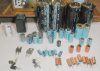
  • sa-7800_parts.jpg
    sa-7800_parts.jpg
    83.8 KB · Views: 165
Last edited:
Here is my list. I found some deviations from the SM on the PSU board and TC board. I replaced it all with the values I found on the boards. All replacements are Nichicon, as were all originals.

Some caps like the 4.7/25V NP were not available at Mouser at the time of order, so I replaced them with 4.7/35V UES caps.

Also, at time of order Mouser did not have UKL types of the low-leakage 0.22/50V but they did have USL types on stock, which after some advise from Nichicon Germany turned out to be low leakage as well. They are "old stock" since they are not produced anymore for a couple of years. The USL's work fine though!

Sorry for the little messy list. You won't be able to import it directly into the BOM tool on Mouser.com. I will need to find out how that works for my next order.

Again, good luck with your SA-7800. Let me know if you need any other info from my SA-7800.

PSU
220uF/100V Low ESR/Impedance UPW C29,C30 Replaced 220uF/80V
100uF/16V Low ESR/Impedance UPW Extra
47uF/63V Low ESR/Impedance UPW C36,C37
2.2uF/50V Low ESR/Impedance UPW C28
4.7uF/50V Low Leakage UKL C34,C35 + 1 extra
100uF/10V Low ESR/Impedance UPW C33
PA
0.22uF/50V Low Leakage USL C21,C22
330uF/6V Low ESR/Impedance UPW C25
100uF/50V Low ESR/Impedance UPW C26
TC
1uF/50V Non-polar UES C39,C40 Replaced 4.7uF/25V NP (deviates from SM)
22uF/16V Non-polar UES C51,C52
10uF/16V Non-polar UES C41,C42 Replaced 22uF/16V NP (deviates from SM)
Indicator
2.2uF/50V Low ESR/Impedance UPW C5,C6,C13
47uF/25V Low ESR/Impedance UPW C10,C12
47uF/50V Low ESR/Impedance UPW C11
47uF/10V Low ESR/Impedance UPW C9
1uF/50V Low ESR/Impedance UPW C3,C4
EQ
3.3uF/25V Low Leakage UKL C1,C2
47uF/50V Low ESR/Impedance UPW C7-C10
470uF/6V Low ESR/Impedance UPW C11,C12
47uF/25V Low ESR/Impedance UPW C13,C14
4.7uF/35V Non-polar UES C23,C24 Replaced 4.7uF/25V NP
 
Last edited:
Mark is sooo fast!

To add: I replaced the relay with a panasonic relay 769-HC4-HP-DC24V. I needed to cut the pins for the "in-rest" throw to make it fit, but the 4-pole fits the PCB after a little squeezing of the inner pins. It actuates 2 poles per channel now which I consider a special treat for the audio signal :). It is a big improvement since the old relay caused distortion and weak bass on the left channel.
Nice to see all the caps lined up Mark! Looks just like my catch :)

Good suggestion to replace the 0.22/50V Low leakage caps with film caps. Which did you use?

I notice the powercap replacements Marks used are currently not stocked on Mouser.com. I have started a search for good alternatives that should need no additional drilling. I will post it when I found THE one :)

And Mark, what is the use of 1uF/100V film caps across the power caps?
 
I think the 1uf caps across the power caps are something to do with filtering. But mark can explain better.

Thanks again guys for the excellent responses.
 
647-LKS1H822MESC 8200uf 50v 6 in stock currently, $7.28 ea

647-LKG1H822MESCBK 8200uf 50v 176 in stock currently, $7.47 ea

sorry, no 63's right now, but the originals WERE 50v...

EVERY available cap has 10mm lead spacing ( I looked - I HATE modifying PCB's) - over 30 years the defacto standard has changed. I forget what the 7800's spacing was, perhaps you could measure and post it?

598-DSF050J224 0.22uf 50v $0.52 ea
I use so many of them , that the price break of $0.14 ea in quantity of 100 was irresistible.

re: 1uf film caps bypassing the big electrolytics - the lytics have inductance at higher frequencies, these film caps have far less. It "cleans up" the signal. A LOT of times the difference is audible. The big filter caps are supposed to be like "black holes", sucking up unwanted signals riding on the power supply lines that change the sound as the amp is operating. Lots has been posted and argued about this. EchoWars uses some 2.2uf caps - apparently the highest capacitance in a reasonable package - , I compromised at 1uf (5989-100V1.0-F) because I could get the caps at $0.50 each in 10 quantity, the difference at the frequencies of interest was small, and being slightly smaller it's a little easier to shoehorn them in.
 
Just spent some time getting the amp board out of the case. Took out the pins of the wire wrapped connecting wires so I wont have any problems with those.

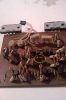
This picture greeted me straight away. Following the traces on the pcb lead to the right hand side output transistor. Not looking good.

attachment.php


I'm gonna clean it all up then look into testing the components. I had a thought about what you said mark and I think thats beyond me right now.
 

Attachments

  • IMAG00212.jpg
    IMAG00212.jpg
    56.1 KB · Views: 134
Last edited:
Some more progress. Both power transistors have given up the ghost. I checked the emitter resistors, all 4 of them measured around 0.4 ohm on my multimeter (i know they should be 0.22), it measures 200ohm scale at the lowest so maybe its inaccurate at lower readings. The other channel's power transistors are fine. I haven't investigated anything else on that side yet, but there is no evidence of damage.

I haven't got far in testing the rest of the transistors yet, but I've done a couple and all are fine. Its getting late here so I think I'll go to bed and have another go tomorrow.

It a shame the power transistors have died, they're terribly difficult to find. Ah well, I always knew it'd end up being something like that.

Now I have the amp completely disconnected from the PSU board would I be able to power it up to check the voltage readings its giving? To make sure they're all present and correct? I know I have a lot of working on the amp board first, but its just something that popped into my head.
 
Last edited:
Those are 150 ohm, 1/2 watt resistors, the emitter resistors for the drivers.

With the outputs shorted, that could fry them.

100 percent testing, even the diodes.
 
647-LKS1H822MESC 8200uf 50v 6 in stock currently, $7.28 ea

647-LKG1H822MESCBK 8200uf 50v 176 in stock currently, $7.47 ea

sorry, no 63's right now, but the originals WERE 50v...

EVERY available cap has 10mm lead spacing ( I looked - I HATE modifying PCB's) - over 30 years the defacto standard has changed. I forget what the 7800's spacing was, perhaps you could measure and post it?

598-DSF050J224 0.22uf 50v $0.52 ea
I use so many of them , that the price break of $0.14 ea in quantity of 100 was irresistible.

re: 1uf film caps bypassing the big electrolytics - the lytics have inductance at higher frequencies, these film caps have far less. It "cleans up" the signal. A LOT of times the difference is audible. The big filter caps are supposed to be like "black holes", sucking up unwanted signals riding on the power supply lines that change the sound as the amp is operating. Lots has been posted and argued about this. EchoWars uses some 2.2uf caps - apparently the highest capacitance in a reasonable package - , I compromised at 1uf (5989-100V1.0-F) because I could get the caps at $0.50 each in 10 quantity, the difference at the frequencies of interest was small, and being slightly smaller it's a little easier to shoehorn them in.

:smoke:

Mark's gig about going to stacked film from the 'lytics for all the 1uf is sooo common in Pioneer it seems.- it SHOULD almost be a sticky! Thanks again Mark.
 
647-LKS1H822MESC 8200uf 50v 6 in stock currently, $7.28 ea

647-LKG1H822MESCBK 8200uf 50v 176 in stock currently, $7.47 ea

sorry, no 63's right now, but the originals WERE 50v...

EVERY available cap has 10mm lead spacing ( I looked - I HATE modifying PCB's) - over 30 years the defacto standard has changed. I forget what the 7800's spacing was, perhaps you could measure and post it?

The spacing in the SA-7800 is 15mm and an extra dummy pin for stability. In the SA-8800 the spacing is 25mm (or close to that). And it has three dummy pins.

I will try the the film caps on the powercaps and let you know if I can hear a difference.

Back to Adrock's SA-7800. Looks like you need to replace quite a bit. If you replace resistors and you choose to use metal film resistors (which are very small compared to these carbon ones), I am very interested in what effect that possibly has on the sound quality or character.
 
Whats the opinion on variations on pcbs? The service manual says something but what I'm looking at and measuring is different.

I'm only looking, at the moment, to get the unit working. If I change one channel of the amp to the service manual spec the other wont be the same.

I hope I have found replacement power transistors for the pair that failed. Paid for them already.

edit : Another progress update. Checked all of the diodes on the damaged channel and everything seems to be fine. I've also tested all of the resistors. The 0.22 ohm resistors, I checked them whilst in the circuit and they were reading 0.4. Checked out of circuit and they are 0.22. Its looking good so far, maybe 4 or 5 resistors are either outside of their values sufficiently or just open.

So now I just need to test the transistors. The ones with 6 legs, are they easy enough to replace? They look scary due to the amount of legs, but I'm sure they'll be ok.
 
Last edited:
Whats the opinion on variations on pcbs? The service manual says something but what I'm looking at and measuring is different.

I'm only looking, at the moment, to get the unit working. If I change one channel of the amp to the service manual spec the other wont be the same.

I hope I have found replacement power transistors for the pair that failed. Paid for them already.

edit : Another progress update. Checked all of the diodes on the damaged channel and everything seems to be fine. I've also tested all of the resistors. The 0.22 ohm resistors, I checked them whilst in the circuit and they were reading 0.4. Checked out of circuit and they are 0.22. Its looking good so far, maybe 4 or 5 resistors are either outside of their values sufficiently or just open.

So now I just need to test the transistors. The ones with 6 legs, are they easy enough to replace? They look scary due to the amount of legs, but I'm sure they'll be ok.

They are just two transistors in a case - not scary - and if you see just 5 leads, they are sharing one lead between the two of them.

I really expect the drivers to have problems.... that's the transistors that are connected directly to the outputs. BUT if they survived, maybe the damage didn't "backflow".
 
Thanks for the tip on those transistors mark, I had an idea it was that and yes they are 5 leads only.

I think I've checked every transistor on that channel of the amp. I'm now looking at the area around the relay, I'm not exactly brilliant with tracing pcbs about so I'm gonna do everything I'm not sure belongs to the other channel.

Q25 (2SA913) was the only other transistor that has blown up. Thats one of the output transistors, right? In your experience could the damage be limited to what I've described? Basically the damage so far is 4 resistors, 1 output transistor and 2 power transistors.

Would it be worth doing the other channel too? The output transistors and the power transistors are all fine. There is no visible damage on the resistors/diodes.

Backlight, re those metal film resistors. I want to keep the amp as near to its original state as possible with components. Mainly because I dont have the time right now to change all of the resistors and it'd eat away at me knowing the channels weren't as close to being the same as possible.


edit: A local component seller is suggesting an MJE15033 as a replacement to the 2SA913.

* DC Current Gain Specified to 5.0 Amperes
hFE = 50 (Min) @ IC = 0.5 Adc
hFE = 10 (Min) @ IC = 2.0 Adc

* Collector-Emitter Sustaining Voltage
VCEO(sus) = 250 Vdc (Min) MJE15032, MJE15033

* High Current Gain Bandwidth Product
fT = 30 MHz (Min) @ IC = 500 mAdc

* TO-220AB Compact Package

* Pb-Free Packages are Available

Thats what I pulled up from the On-Semi website. You reckon those look ok to replace? Never had any experience with On-Semi, they ok?
 
Last edited:
I would recommend to keep both channels identical if you want to have balanced and high fidelity audio. Different transistors result in different sound, maybe just a little, but enough to significantly affect the stereo image, sound stage, positioning of instruments etc...

In addition, if you replace the 2SA913 with a different type, even if it is another 2SA913 (different brand, production batch/year etc), make sure you also change the complementary transistor (Q23/2SC1913) which drives the other output transistor for that channel. And consequently change the driver transistors of the other channel too (Q24 and Q26) with the same replacements.

Mark makes some recommendations for substitutes earlier in this thread. I suggest you follow his suggestions first. I came across a substitute list that mentions a 2SC1111 and 2SC2591 as substitutes, but no guarantees; you have to try and hear if they are good (enough). These are available on ebay after a search from an old stock supply.

There are still 2SA913 and 2SC1913 transistors available in webstore like donberg electronics (try google). But they are 120MHz, quite expensive and are from a different make (not sure what) than the originals, so again here, you have to try and listen...

Good luck!
 
<grumble> WHY don't people READ what I POST???????????


2sa913 to-220 bce 180v 1a 15w 65-330hfe 120mhz

I posted this last page:

****************
757-2SA1930(Q,M) pnp to-220 bce 180v 2a 20w 200mhz 50-320hfe 200mhz nsa driver
757-2SC5171(Q,M) npn to-220 bce 180v 2a 20w 200mhz 50-320hfe 200mhz nsa driver
these seem to be the best choice PLUS mouser stocks them!!!!
*************

because the ksa940 was too slow...

it's a mouser parts number...
 
As you pointed out mark, they were cryptic notes ;) I got lost in them.

Thanks for pointing it out to me though. I'll take a look at the mouser site now and get ordering, I think.
 
Local shop stocks both of those transistors you suggest mark. Looks like I'll be purchasing them there.

For the resistors, apart from the 150 ohm 1/2 watt ones can the rest be normal 1/4 watt?

Mouser's carriage to the UK is prohibitively high for the small (i hope) amount of things I need.

I'm gonna have to survey the rest of the amp first before diving in though. I asked a bit back if I could power the unit up without the amp board in it. The electrician in me says no load = safe but knowing electronics and the voodoo of balancing it all, it'll go into meltdown. What do you reckon mark?
 
That's good luck the transistors are local.

Off the top of my head, it should be safe if all the disconnected wires are insulated.

Check the resistor codes in the service manual, but most are 1/4 watt.

Flameproof usually has a triangle, and wattage shouldn't be increased.

That whole d^%^ amplifier circuit is cryptic... till you get to know it.
 
Replaced the output and driver transistor pairs for both channel. I know you've suggest replacement for the power transistors, mark, but I cant seem to find them anywhere.

I have managed to find a source for 2SA1216 and 2SC2922. Here are the links to the datasheets for them :

http://www.sanken-ele.co.jp/en/prod/semicon/pdf/2sa1216e.pdf
http://www.sanken-ele.co.jp/en/prod/semicon/pdf/2sc2922e.pdf

I'm no expert with datasheets but they seem to be 10mhz slower than the 1215 and its counterpart.

I also plugged the unit in, being careful to make sure all of the pins were not in danger of shorting either together or to ground. All of the PSU voltages seem to be in perfectly good order aswell, so thats an added bonus.

Awaiting the arrival of the 'original' power transistors. If they dont arrive I'll be looking at substitutes of a suitable caliber to closely resemble the originals.
 
Last edited:
Back
Top Bottom