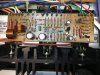
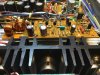
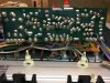
It appears to me that the differential amplifier formed by Q3 and Q4 is out of balance since the collector voltages should be identical under normal conditions (ie. no significant DC offset present). With the base voltages on Q3 & Q4 both being 0V, the differential amplifier should be balanced and not in protection. Since it is not, one would first suspect Q3, Q4, R13 or R14. But those were either replaced (Q3,Q4) or tested good (R13, R14). So, someting else must be causing the collector current imbalance.
Here's one more check to make. First, return all resistors and diodes to normal. Then with the power off, watch the pin 16 voltage until it's been completely bled away. Then measure the resistance from pin 16 to the collector of Q3 and Q4. They should be very close in value confirming that there are no continuity issues.