• The move to the new server is done. There are some software and database maintenance updates in process. This has us passing the hat around to help out. We appreciate any donations. Seriously, even a dollar helps. The payment page may be found here - https://www.audiokarma.org/support.html

SA-9800 fluorescent display issue

ok, ok, ok! you are very clear now! Didn't understand "how to proof it"... I am not an electronics expert or engineer. I have had some during my Maritime degree but that mainly focused on electric motors, generators, switches and control panels. I am learning here.

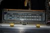
But before I start making the measurements of all I want to show you the picture of the display itself. In the left top corner some dark "blueish" film has accumulated on the inside of the glass. Could be a result of burn or bad contact, but behind it is nothing visible (looking from an angle with a bright light). It's just the glass.

The four ultra thin wires across the display are clean and tight.

Could this be the indicator of a dying display, together with the voltage variances over time?

I will start making the measurements. Thanks for your help!
 

Attachments

  • IMGP7371.jpg
    IMGP7371.jpg
    55.4 KB · Views: 119
<snip>

But before I start making the measurements of all I want to show you the picture of the display itself. In the left top corner some dark "blueish" film has accumulated on the inside of the glass. Could be a result of burn or bad contact, but behind it is nothing visible (looking from an angle with a bright light). It's just the glass.

The four ultra thin wires across the display are clean and tight.

Could this be the indicator of a dying display, together with the voltage variances over time?

I will start making the measurements. Thanks for your help!

It is a small possibility,

The film inside of the glass is most likely spillover from a "getter".

Pumping out air to make a vacuum only goes so far, so after the tube is sealed, a "getter" is heated which hopes to vaporize some metal leaving behind a reactive film that will chemically bind (burn) the leftover gases in the tube.

http://en.wikipedia.org/wiki/Getter

It can be a source of problems, as it IS a conductive film, and heat will migrate it... That in fact is one of the failure mechanisms, sort of like inside of a neon bulb, a neon bulb gradually gets a metallic coating from it's electrodes all over the inside of the glass that darkens it and actually shorts it out internally.

Generally tho, that is there from manufacturing, and probably hasn't changed, unless some sort of internal defect is manifesting.

I suspect the issue that cooked the burned area of the power supply board is cooking that resistor all over again. My bet is on bad design.
 
Interesting to learn about this vacuum process.

The measurements now. The first 6 are taken from power up with an interval of 5 minutes. The 7th value is taken 30 minutes after the 6th. At this time the display brightness is very low. All with brightness switch to bright.

awr-194 pin 13 to metal chassis ground DC voltage
66.2 --> 66.3 --> 66.0 --> 66.0 --> 66.0 --> 66.0 ------> 66.6

awv-002 pin 10 to metal chassis ground dc voltage
34.2 --> 43.0 --> 45.9 --> 47.3 --> 48.1 --> 48.5 ------> 49.4

awr-194 pin 3 to metal chassis ground DC voltage
52.0 --> ... all other measurements same value

awr-194 pin 5 to metal chassis ground DC voltage
32.2 --> ... all other measurements same value

awr-194 pin 7 to metal chassis ground DC voltage
19.0 --> 19.1 --> 19.2 --> 19.2 --> 19.2 --> 19.2 ------> 19.2

awr-194 pin 26 to metal chassis ground DC voltage
0.0 --> all other measurements same value

awr-194 pin 25 to pin 27 AC VOLTAGE
3.7 --> 3.7 --> 3.7 --> 3.7 --> 3.6 --> 3.6 -----> 3.7

Across R23 AC voltage
6.0 --> 6.0 --> 6.0 --> 6.0 --> 5.9 --> 5.9 -----> 6.0

The big changes are on PIN 10 on the awv-002 board.
 
I currently have a beautiful SA-9800 (belonging to a member here) with the same issue- happened suddenly after shipping. All votages are fine, and ramping up heater voltage slightly has made no difference. I can only put it down to a loss of vacuum. The glass panels are fused together with some form of adhesive, not melted glass, and I believe the vacuum has collapsed resulting in no emission. There is one little thing you might like to try though- check the brightness switch for correct functioning on both sets of poles - it uses three out of the four and oxide buildup happens due to the relatively high voltage on it. It is a nightmare to get to, but it can be done. I suggest probing the brightness switch contacts for continuity on both positions or temporarily jumpering them
 
Thanks John for you help. I have de-oxit the bright switch. I will try bypassing the switch in both position to see if it can carry the current.

What happened to the display of you r beautiful SA-9800? Did it completely dim, so no display at all? Or, like in my case dims to an low brightness display in about half an hour on time, but the display brights up again after disconnecting the 30-50 volts line (PIN 10)? Because the display is capable of showing normal bright segments, I doubt whether the tube has lost its vacuum. It's just not stable at the moment in correlation with the circuitry that feeds the voltages and currents.

An additional comment about the display "getter". I checked the display of my SA-7800 for getter and this display show a same "spot" on the same place, so Mark is correct that is is likely to be spilled getter during the tube vacuuming process.
 
<snip> Because the display is capable of showing normal bright segments, I doubt whether the tube has lost its vacuum. It's just not stable at the moment in correlation with the circuitry that feeds the voltages and currents.
<snip>

Ok, with that piece of logic in place, the conclusion is inescapable:

The 0v bias on the heater is stable, and goes DIRECTLY to the tube

The heater AC voltage is stable, and goes DIRECTLY to the tube

The 19.1volts to the individual segments is stable, and goes DIRECTLY to the tube segments

The 66v power from the supply is stable
BUT
it does NOT go directly to the tube.
the circuitry that feeds the voltages and currents
it goes through some resistors.

The 390 ohm 1 watt resistor and the 1.2k ohm 2 watt resistor on the protection assembly awm-163 with the bright / dim switch are in the way.The "funny" thing is that bright is MORE resistance (less pin 10 voltage) and dim is LESS resistance (more pin 10 voltage).

you start off with a "balance" being struck between the internal resistance of the tube and the resistance of these resistors. The expression of this balance is the 34.2v you measure at the awv-002 display board's pin 10.

THE conclusion:

Either the tube is changing
OR
the resistors are changing.

The resistors are common, the tube is not. If changing the resistors does not have an effect, the tube is to blame.


The resistors have (66.2 - 34.2) 32v across them, having a current of (32 / (1200 + 390) ) 0.020 amps ... 20mA. At that point the pair of resistors is dissipating (32 * 0.020) 0.64 watts which the resistors should be handling as they are respectively 1 and 2 watts power dissipation.

At the dim point we have (66.2 - 49.4) 16.8 v across them, a current of (16.8 / (1200 + 390) ) 0.010 amps ... 10mA. At that point the pair of resistors is dissipating (16.8 * 0.010) 0.17 watts.

This means that the resistors aren't being worked hard to their limits.

we have one last trick up our sleeve for testing.

the bright/dim switch has been kept in the bright position all the time by design. now it's either time to take the measurements that you did above with the switch in BOTH positions and see what happens with all the voltages.
(pin 26 will start not being zero!! in the dim position)
bright is MORE resistance (1590 ohms), dim is LESS resistance of 1200 ohms by 390 ohms. Ohms law might reveal if one of those resistors is changing value.

Can you measure (see) the resistors during operation? so instead of measuring pin 10 voltage during bright and dim, you could measure the voltage in between the two resistors? Perhaps at the bright/dim switch itself?

***************************************************
OR you could replace those two resistors - since your change did come on suddenly which indicates some sort of failure. There could still be something else mechanical (heat related?) happening in that area because nothing has been disturbed since you did the work.
***************************************************

One other thing to try, but I fear external influences will make this impossible to do, is to take a resistance reading between pins 9 & 10 of the awv-002 display board when cold, and then quickly when hot and dim...

 
Last edited:
My logic has always surprised me! :) But I meant PIN 10, as you say. All the others are stable.

Thanks for the thorough analysis. I will do the readings on the resistors this evening.

A little more of my logic:

What about the 19.1 volts to the segments. Is it possible that this is too high, even just 1 volt. And this causes the display to behave different over time when heating up? (with a memory) If I understand how the zener/resistor combination works as a voltage regulator this can be lowered with a lower voltage diode.

And the transformer AC output of 3.6 volts? which also is higher than according spec. Replacing R23 on the PSU board can reduce this voltage if I understand correctly. Could that affect the display operation? I have a 1/2watt 390Ohm metal film resistor at hand.

I have the impression the display dims faster when more segments are lit. I tested this with music playing on high volume with no speakers connected (Speakers switch in off position).

I don't have replacement 1.2kOhm (2W) and 390 Ohm (1W) resistors at hand. If I order these, does it make sense to buy an additional higher resistant replacement for the 1.2K one? The voltage on pin 10 seems to go to about 50volts stable (after some time) in operation (bright position). If we aim at a value of 34 volts, what would the replacement value be?

I don't understand how the display works. Disconnecting pin 10 resultsin a bright display, but with blurry edges on the segments. From a distance you don't notice that, so it could be acceptable. But what is the function of this voltage? Having all the other voltages as well: 3.6 for the heater and 19.1 for the segments?

Not forget the 16.5Volts DC on PIN 6 of the indicator board. This is fed from the rectifier board and holds voltage for a while (down to 5VDC in about 10 minutes) after shut off.

Apologies if I suggest some impossible things and make unlogical assumptions. :scratch2:
 
I have done some measurements:

After playing the amp for about one hour the display is quite dimmed and the readings are as follows (switch in bright position):

awv-002 pin 10 to metal chassis ground dc voltage: 51.3 Volts
awr-194 pin 13 to metal chassis ground DC voltage: 65.8 Volts
Across 1.2K resistor: 10.9 volts
Across 390 resistor: 3.4

Then I disconnected pin 10 and played the amp for some time and switched it off to let it cool down a bit.

Reconnected pin 10 and switched and had the following readings (switch in bright position):

awv-002 pin 10 to metal chassis ground dc voltage: 41.9 Volts
awr-194 pin 13 to metal chassis ground DC voltage: 65.8 Volts
Across 1.2K resistor: 18.7 volts
Across 390 resistor: 5.8

They might be a bit off because during the readings the voltage on pin 10 increased steadily and I am unable to measure all voltages simultaneously. If I leave it off longer the voltage on pin 10 starts lower at around or just below 30 volts.

Next I will measure the resistors and pin 26 while operating the dim switch.
 
I'm getting to the point that I want to change direction... measuring is not satisfactory. Starting with measuring with switch in both dim and does not affect the voltages, only the voltage on pin 10...

I want to replace the two resistors to pin 10 (390 switched and 1.2) and the resistor/zener diode on the PCB regulating the 19.1 voltage to make it regulate at 18 volts. If that does not solve the issue I either live with a dimmed display or look out for a spare display from another (broken or destroyed) SA-9800.

I also want to have an additional replacement of the 1.2K resistor of higher value to reduce the stable voltage on PIN 10 from 52 volts to 40 volts. I need a recommendation for this 2W resistor value.

In addition I need a recommendation for the replacement zener diode on the PSU board. Which is best?

:sigh:
 
I have NOT had time to analyze your previous posts.
edit- but that voltage on pin 10 IS the key and is the ONLY measurable difference or symptom.
see the bottom:

BUT, from subsequent to my last post's research, here's an experiment.

I hope it is safe, and i think it is because the sx-3900 has a similar indicator wired as such:
heater transformer center tap is grounded (= pin 26)
heater run at 3.5v ac or so (= pins 25 & 27)
segments run at 12.8 volts ( = pin 7 19.2 volts)
and finally for "pin 10"
"grid" connection is also 12.8 volts, with a 5100 ohm resistor (= pin 10)
that is shorted in BRIGHT position to allow 12.88 in, and when in the DIM position the resistor has 8.48v(1.662ma) across it in dim with no audio and 8.22v(1.611) with almost all the segments lit.

that's IT on the 3900,
to DIM the display, a 5100 ohm resistor resistor drops the voltage on "pin 10" from 12.8 to 4.4 volts.

so here's the experiment:
with pin 10 disconnected, take your meter, set it to measure current and connect one lead to the 19v point, and then touch the other lead to pin 10.
watching out for:
1. a huge increase in brightness
2. a huge amount of current (over 30 mA)
if so, stop - we don't want to damage the display

see what happens over time, watch the current for increases. watch the brightness, be very cautious.

edit: before messing with the 19v, you could get a pair of 17v zeners and connect them in series with the top cathode to pin 10 (and the bottom anode to ground) because the current drawn through the resistors DECREASES, increasing the voltage and decreasing the brightness. The zeners will see the voltage try to rise, and draw that extra current through themselves instead of the display using it, trying to keep 34 (17 x 2) volts across themselves at pin 10. the detraction is that the bright/dim switching of those resistors wouldn't change the brightness anymore.
 
Last edited:
That is a nice experiment Mark! I will do that this evening and report back. If that gives a clue to a solution it would be a pleasant surprise.

If it doesn't, I consider the above: replacing the components feeding Pin 10 and Pin 2 on the indicator board and the resistor/diode regulator (located on the protection board) on the heater transformer center tap (Pin 26 on the PSU board).

Results of the experiment later today...

Another question: Could somebody with a SA-9800 (with a bright screen), measure the DC voltages against ground/chassis of Pin 10 and Pin 2 of the indicator board, switch in bright position? You only need to remove the cover of the amp... I would really appreciate this as a benchmark for a normal functioning display. Please!
 
Last edited:
The results in this nice experiment:

After wiring the meter as Mark said, with the meter connector to pin 10 still loose I turned on the amp and connected the meter briefly. I read somewhere between 8 and 9 mA. So I assumed that ok. I connected the meter steadily with a clamp (crocodile). The current looks quite steadily when no change in segments. It drifts 0.1-0.2 mA sometimes, but that's all. When I turn up the volume however (so all segment light up) the current decreases. Here my readings over time:

Switch bright:
No power segments lit: 8.9mA
All power segments lit: 8.4mA directly and after 10 minutes it settles at 6.9mA
The other way around: 6.9mA -> 7.4mA -> 8.9mA

Switch dim:
All power segments lit: 5.9
No pwer segments lit: 6.3mA directly and after 10 minutes 7.0mA
The other way around: 7.0 mA -> 6.6mA -> 6.6mA

The last reading surprised me since I expected the current to drop further to 5.9mA. Apparently it found a different balance as directly after being switched from bright position.
 
The results in this nice experiment:

After wiring the meter as Mark said, with the meter connector to pin 10 still loose I turned on the amp and connected the meter briefly. I read somewhere between 8 and 9 mA. So I assumed that ok. I connected the meter steadily with a clamp (crocodile). The current looks quite steadily when no change in segments. It drifts 0.1-0.2 mA sometimes, but that's all. When I turn up the volume however (so all segment light up) the current decreases. Here my readings over time:

Switch bright:
No power segments lit: 8.9mA
All power segments lit: 8.4mA directly and after 10 minutes it settles at 6.9mA
The other way around: 6.9mA -> 7.4mA -> 8.9mA

Switch dim:
All power segments lit: 5.9
No pwer segments lit: 6.3mA directly and after 10 minutes 7.0mA
The other way around: 7.0 mA -> 6.6mA -> 6.6mA

The last reading surprised me since I expected the current to drop further to 5.9mA. Apparently it found a different balance as directly after being switched from bright position.

Did it look "normal" initially? How about in the "dim" position, which is now only the part of the circuit that effects the cathode/heater with the 470 ohm resistor and 8v zener diode to ground, instead of directly grounding it?

I take it that the circuit is "cooking" now....
 
Last edited:
Do you mean if the display looked normal initially? Yes, the display looks normal in both bright and dim position. A slight difference in brightness on the left and right side of the screen (gradually), which shows more in bright position than in dim, but response ok and no blurry edges.

The difference between dim and bright is just little since the only thing that is changing is the switch on/off of the 470 Ohm and zener diode.

I can't see if the 470 ohm resistor is cooking in dim position. It's too hidden.

I think I would like to replace the following:

- R7 470 ohm 1/2w resistor and D5 8v zener diode (protection board)
- R9 1.2 Kohm 2W and R8 390 ohm 1W (protection board)
- R20 330 ohm 1W and D10 zener diode (PSU board)

Two questions:
1. what are the best zener diode values? especially D10?
2. What is a good replacement for R9 so the voltage on PIN 10 will be around 34 volts in bright position. I was thinking something in the order of 2.0 Kohm and keep R8 at 390 ohm.

If that does not results in a satisfactory display, I will live with it and look out for a spare display. Perhaps somebody on Audiokarma has a SA-9800 for spares? :)
 
I have a completely different idea. I am going to "take care of" their "shortcut" in design - using a series resistor to drop voltage - THEY ASSUMED that the current drawn by the display over time would stay constant. It HASN'T.. thus this "mess".

I am working on it to include the bright/dim switching, but it involves a transistor regulator for the pin 10 voltage - now don't get all worried about that, it's just usually 2 resistors and a transistor - just like - say- the lower voltage regulators in say a sx-950 or 1050. SIMPLE.. It will keep pin 10 constant, and the working on it part is getting the bright / dim switching integrated in and operating.

The target is the bright and dim voltages, when the display is cold and working correctly.
Dim IS a higher voltage...

I'm even trying to do it without having to change R8 & R9, although that may be wasteful of current. A resistor that IS the resistance of the tube at that point in time (plus a little bit for the 0.6v turn on bias of the transistor).

The result will be a constant voltage on pin 10 (the emitter of the transistor) that will STAY constant no matter what the tube does (within reasonable limits of course), and have a bright constant voltage, and a dim constant voltage.

Right now things are too dependent upon the internal conditions of the tube.

One volt difference between 18v and 19v is within EXPECTED manufacturing tolerances.
 
Last edited:
Sounds good to me. If it is doable to keep the voltage on PIN 10 stable with a transistor regulator I will be very happy to build that in somewhere on the board, or create a new board with the two resistors an transistor. And I am even happier when the dim switch is still operable to "dim" the display. I know the voltages on pin 10 increases to dim the display (R8 is bypassed), while Pin 26 (PSU) is no longer grounded but goes through the R7 and D5 regulator.

D5 has been replaced by the previous owner and I believe it is a 5V zener diode since Pin 26 reads about 5V in dim position. But I am not sure how that works...

But Mark, if you tell what to "build"in as simple as possible steps, I will build just that... :)
 
I have been curious and can contain myself no longer....

How did the display look after a few hours of operation, when it normally would have dimmed ?

And after that time, what were the current readings on the meter???

I also have the preliminary information about the addition of the transistor regulator:

On the awm-163 protection assembly, pins 9 to 11, a 1600 ohm 2 watt resistor is added.

The wire from pin 9 on the awm-163 protection assembly going to pin 10 of the awv-002 indicator assembly is interrupted. This wire will now go to the base of an NPN power transistor.
Instead, the emitter of that NPN power transistor will be connected to pin 10 of the awv-002 indicator assembly

Finally a NEW wire is needed from the collector of that NPN power transistor to the +68 volts, either from pin 6 of the awm-163 protection assembly or pin 13 of the awr-194 power supply assembly.

Then all you need to do is to figure out where to mount the transistor, and either put a heatsink on it, OR do an INSULATED mounting to the metal chassis somewhere convenient to carry away the heat.

The transistor will be an NPN power transistor capable of handling 100 volts, over 100 milliamps and dissipating up to 4 watts of power (or more). It can be to-220, which will need insulating - because the metal case is energized, or it can be a TO-126 case, which would NOT need insulating.

We MIGHT want to add a small capacitor 20 to 47 uf (80v) across the 1600 ohm resistor, which will then closely imitate the sx-950's Q5 regulator circuit and preclude any chance of oscillation.
 
Thanks a lot!

I assume you mean how the display behaved over time with the 19.2 VDC on Pin 10 (indicator board) through the meter?

I did not play the amp for hours since it is not part of my main system currently. My SA-7800 took that place temporarily. (My SA-8800 is in my TV room by the way). But if I remember the response of the display over about half an hour time in bright position, the display showed a slight difference in brightness from left to right gradually, where left was brightest. Is this an answer to your question?

About the circuit you propose:

Adding a resistor (1.6K 2W) from pin 9 to 11 on the protection board causes a decrease voltage on pin 9 since pin 11 goes to ground, am I correct?

Pin 9 is influenced by the brightness switch, switching the 390 ohm resistor, so I think I am with you that this is needed input for the transistor. The transistor consequently amplifies this using the 68VDC feed (from somewhere...I will figure that out :)). The emitter is connected to Pin 10 on the indicator board.

I think I understand the operation. A couple of questions:

1. To what voltage is this regulator regulating?
2. What if we replace the 1.6K resistor with a variable resistor that can handle 2W dissipation? That would mean the voltage to Pin 10 on the indicator board can be adjusted easily.

I have a couple of new BD241C transistors laying around. If I look at their datasheet they should do the trick. Am I correct?

I have Arctic cooling MX-2 cooling paste. Would this sufficiently insulate the transistor? According to the specs this paste is non conductive since it does not contain metal particles. The side for the screw I can insulate with a piece of plastic.

Additionally I would also like to replace the two diodes mentioned earlier. What do you recommend here? I am building an order list for mouser.
 
Adding the 1600 ohm resistor from pins 9 to 11 forms a voltage divider at pin 9, and it is calculated to give about 35 volts at that point. And the dim switch increases the voltage, as intended. These values are from your "cold" and "looks good" tests of bright and dim voltages. It is the approximate resistance of the cold tube, based on the cold current draw.

The extra transistor will try to keep it's emitter voltage 0.6v or so greater than the base voltage, and will adjust it's conduction to maintain that 0.6v difference. Adjusting it's conduction will feed more or less current into the display to keep the emitter voltage constant even though the display is now an inconstant load. In other words, a crude voltage regulator.

Yes, you could put in a pot that handles 2 watts. OR you could scale all the resistances up by a factor of ten, and use lower wattage resistors.BUT that means changing the two resistors (1200 ohms and 390 ohms) on the protection board as well to keep the bright and dim voltages the same - complicating things a bit.

The BD241C will be fine, but you WILL need a sil pad OR mica insulator, just grease is insufficient.

TO-220 mounting from mouser:
..... 532-7721-7PPS to-220 mounting shoulder washers, 4-40 $0.29 ea
..... 534-4672 to-220 mica insulators $0.12 each...........
..... 532-4880SG @ $0.91 with sil-pad insulator, screw, washer, lock washer, insulating shoulder washer & nut.
..... 532-4880 @ $0.77 with thermal film insulator, screw, washer, lock washer, insulating shoulder washer & nut.
..... 532-4990M @ $0.77 with mica insulator, screw, washer, lock washer, insulating shoulder washer & nut.

D10 psu wz-177 is 17.7 volts
512-1N5247B Fairchild 17 V 0.5W Zener (min 16.16v typ 17.0 to 17.85vmax)
or
512-1N5248B Fairchild 18 V, 0.5W Zener (min 17.1v typ 18.0 to 18.9vmax)
(see why I wasn't worried about the 19.1 volts??)

D5 prot mz-081 is 8 volts
512-1N5237B Fairchild 8.2V, 0.5W Zener (min 7.79v typ 8.2 to 8.61vmax)
 
Last edited:
Backlight, the 9800 I have failed suddenly and after transport- hence my opinion of lost vacuum. Heater is fine as are the majority of voltages.
I have just contacted Pioneer in Japan to see if they happened to have a tube floating around- got a very fast response via Australia, but no tube :( sadly.
I have found one in the US but the guy wants over US$100 for it plus postage. ouch!
Frustrating to say the least.
I'd love to get some accurate readings from a working 9800 display board too.
 
Back
Top Bottom