• The move to the new server is done. There are some software and database maintenance updates in process. This has us passing the hat around to help out. We appreciate any donations. Seriously, even a dollar helps. The payment page may be found here - https://www.audiokarma.org/support.html

SA8500 only works on DBT

Have you tried adjusting the dc offset (from 210-240mV) using VR3 and 4
as per chapter 8.1. You can skip the 5.1k short/resistor just to ballpark.
Does the offset respond to adjustment?

Referring to the sm, the amp has,
- Over Current Detection
Measure voltage between Pin 1(red) and pin 2 (black) on power amp board
Measure voltage between Pin 8(red) and pin 2 (black) on power amp board
Measure voltage between Pin 9(red) and pin 16 (black) on power amp board
Measure voltage between Pin 15(red) and pin 16 (black) on power amp board
(don't expect much)

Has C20 (100uf/16V) and C21 2.2uf/25V in protection circuit been replaced?
Long shot that C21 is breaking down under the extra voltage

Still need to check out voltage inbalance as per sm.
 
Have you tried adjusting the dc offset (from 210-240mV) using VR3 and 4
as per chapter 8.1. You can skip the 5.1k short/resistor just to ballpark.
Does the offset respond to adjustment?

Referring to the sm, the amp has,
- Over Current Detection
Measure voltage between Pin 1(red) and pin 2 (black) on power amp board
Measure voltage between Pin 8(red) and pin 2 (black) on power amp board
Measure voltage between Pin 9(red) and pin 16 (black) on power amp board
Measure voltage between Pin 15(red) and pin 16 (black) on power amp board
(don't expect much)

Has C20 (100uf/16V) and C21 2.2uf/25V in protection circuit been replaced?
Long shot that C21 is breaking down under the extra voltage

Still need to check out voltage inbalance as per sm.

C20 was replaced with a 100uf 25v upw nicicon
C21 was replaced with a 2.2uf 50v ukl nichicon

Pin1 and Pin 2 = 85.5mv approx
Pin 8 and pin 2 = 172mv approx
Pin 9 and pin 16 = 72 mv approx
Pin 15 ans 16 = 70mv approx

I have not touched the trimmer pots at all, i believe the VR number sin manual are incorrect - some SM error - think wherever manual says VR1 or VR2 it means VR3 and VR4, also meaning wherever manual says VR3 or VR4 it means VR1 and VR2.
I am not 100% sure on this
 
Last edited:
from what i read already it went bad after working on tone board . all i can think is power supply is failing or something . a list of supply and protect voltages should help here

I can start taking measurements from each pin - red probe with neg probe to chassis if required, no problem at all, thanks

Power Amp Board - Neg to chassis all DC voltages
Pin 44 = 45.8v
Pin 18 = 46.2v
Pin 31 = 46.1v
Pin 17 = 52v

AWS-085
(all approximate values due to bit of jumping around unless specifically noted to be stable)
Pin 11 = dropping in mV toward 0
Pin 12 = 41.7mv
Pin 13 = 42.7mv
Pin 14 = 46.2mv
Pin 15 = 45.8V Stable
Pin 16 = 45.8v Stable
Pin 17 = 46.1mv
Pin 21= 225mv
Pin 22 = 220mv
Pin 23 = 230mv
Pin 24 = 220mv
Pin 25 = 0 Stable
Pin 26 = 150mv
Pin 27 = 300mv
Pin 28 = 300mv
Pin 29= 160mv

Filter cap voltages - measured between neg and positive of each cap separately
46v and 45.9v
 
Last edited:
You will also want to check the regulated power supply pins 34-39 on AWS-083. Your measurement of pin 17 on the power amp board is too high (52V which should be 35V). Q1 on AWS-083 may be shorted C-E.
 
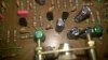
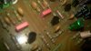
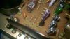
I'm with pete...has to be something related to the tone board. How about the transstors that you replaced...were they the same pinout? Could you possibly have installed one wrong? I did on some unit at some point...I had been having to reverse the visual orientation on a bunch of replacements (I think C458 when replaced with C1845), but then reversed the orientation on another that I DIDN'T have to. Discovered it by taking a close look at before and after photos....

EDIT: It was a Pioneer SA-8500II I had reversed one that shouldn't have been (however, it was on an amp board, not the control board). The one's on the control board that were replaced did need to have a different orientaion however, so go back and check that things are really correct there!

Here's my rebuild, the discovery of the wrong Q orientation is on p. 4.
 
Last edited:
I'm with pete...has to be something related to the tone board. How about the transstors that you replaced...were they the same pinout? Could you possibly have installed one wrong? I did on some unit at some point...I had been having to reverse the visual orientation on a bunch of replacements (I think C458 when replaced with C1845), but then reversed the orientation on another that I DIDN'T have to. Discovered it by taking a close look at before and after photos....

EDIT: It was a Pioneer SA-8500II I had reversed one that shouldn't have been (however, it was on an amp board, not the control board). The one's on the control board that were replaced did need to have a different orientaion however, so go back and check that things are really correct there!

Here's my rebuild, the discovery of the wrong Q orientation is on p. 4.

Yes had to reverse pretty much all of the given the different pin outs of the replacements.
An 180 degree turn basically. The 2sa725s are ECB, the ksa992fbu I used to replace are BCE.
The 2sc1312 are ECB and the ksc1845fta I used to replace are BCE
 

Attachments

  • IMG_20181216_155729.jpg
    IMG_20181216_155729.jpg
    65.6 KB · Views: 10
  • IMG_20181216_155658.jpg
    IMG_20181216_155658.jpg
    51.4 KB · Views: 8
  • IMG_20181216_155640.jpg
    IMG_20181216_155640.jpg
    55.4 KB · Views: 9
  • IMG_20181216_155623.jpg
    IMG_20181216_155623.jpg
    70.2 KB · Views: 9
  • IMG_20181216_155614.jpg
    IMG_20181216_155614.jpg
    64.8 KB · Views: 8
it is all in the details.
That is correct, I pull one, then use the new one to compare against the old one, which I turn 180 degrees to each other, form the leads on the new one to match the old one lead forming, solder, double check.
At least they show the pins on the pcb as your guide, but always check before to verify that what they printed on the pcb is correct to begin with.
 
I use photograph, transistor test original, transistor test replacement, and replace accommodating for difference in pinout if any.
Replaced the 2sa726 on power board with kas992fbu.
Still have the 52v on pin 17
 
Did the bias bump up and the dbt is limiting it just enough to kick it ??
Weird one here for sure....

That's my suspicion, and the DBT is dropping voltage enough so the protection isn't triggered. That same 35V supply which is now too high also supplies the protection circuit, throwing it all out of cal with 40% more voltage.

Yes, worked all the way up until after did the tone board. And on dbt at the moment will work musically also. But on mains relay does not click. After doing this board. In fairness there are bunches of caps in need of replacement.

Don't forget this facet - It operated until the tone board was reworked.

With high voltage on the AWS-083 board Pin 39, I'd suspect an issue with Q1 on that board. That would include the voltage divider network formed by R4/R5. If Q1 is injured, a KSD526Y or MJE15032G should work.
 
I'm confused folks I apologise -
Q1 on awh042 is a 2sa725
Q1 on aws085 is a 2sc1621 - did not replace
Q1 on awg034 is a 2sa725

All 2sa725 were replaced with ksa992fbu is that correct?
 
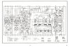
Oh, this is a "foreign" model, eh? A KSD526Y is still plenty. Don't forget this:

574102b00000g.jpg
 
Last edited:
Back
Top Bottom