• The move to the new server is done. There are some software and database maintenance updates in process. This has us passing the hat around to help out. We appreciate any donations. Seriously, even a dollar helps. The payment page may be found here - https://www.audiokarma.org/support.html

SA8500 only works on DBT

36V is certainly close enough (±3%) to call it done. Hopefully, that resolves any other problems you might be experiencing. However, due to the relationship between this power supply and the amplifier stages, it would be a very good idea to check/adjust the bias voltage and idle currents, following the service manual instructions.
 
Yes, powered up, pushed for time to get this done for Christmas, so have the adjustment pots to change, the sc1451's and that's it finished. Filter caps also done. All dialled in now and tested for a few hours, savage unit, really nice sound.
I am so thankful for all the help truly
 
Hey all, i am resurrecting this thread to talk about a bulb issue - basically the bulb i bought from Dwojo was a 12v bulb which i installed on my friends unit. It has since stopped working, so i opened it up, evidence of a lot of heat on the resistor which is beside the bulb itself as the shrink wrap is melted.

So i check the voltage between pins 8 and 10 - approx 45VAC!
I have contacted dwojo, i know this is certainly not his bulbs fault.

Can someone shed any light on this? I am assuming the 45VAC is not correct - another thread i read stated 35VAC.
Am i needing to put my own resistors in place when installing an LED for the SA8500?
I only need the bulb to live a long time, just as long as my friend can see the unit is on he doesnt want it too bright.

Hope you can all help, thanks as always
 
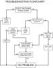
What flow chart do you mean?
This one:
flowchart.jpg
Could not resist even if it was an older post just resurrected . . .

Is this an SA-8500? The voltage across pins 8 and 10 of the power supply board should only be about 8 vac. If your meter black lead is clipped to chassis/ground pin 10 should be 0vac unless the ground has opened up. If the bulb has failed (open) no current will flow through it, so there will be no voltage drop across R8 (750Ω 3W), then you will see the full ac voltage from the transformer winding on pin 8. ≈35vac (or more) would not surprise me. Replace the bulb and measure again. The max voltage drop the resistor can handle is about 47v at its rated 3W power level. 35v - 8v = 27v, for just under 1W dissipation for 750Ω at rated schematic numbers.
Putting in an LED is a bit more complex, you will need an LED or 2 (of course), a diode, another resistor or different resistor for R8, and maybe a capacitor. What LED did you have in mind?
 
Last edited:
Howdy I just bought an 12v led from Ak member dwojo, our resident bulb guy.
So I have no real idea of the spec on it. I have spoken to him since and he has recommended putting a 1k resistor in before the bulb.
I had no idea I needed a diode or an additional capacitor, I would not have a clue how to wire that up, and I know to you guys it is so simple, so please go easy on me
 
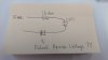
View attachment 1547174

Would this work? Does the second diode then protect the led from reverse voltage?

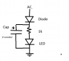
That is close, here is how I would do it:
ledaddition.png
A 10 mf (or greater, not critical) cap will reduce flicker if you have any, not required, make sure it has a high enough voltage rating, 60vdc should be good enough for your application, better 100vdc if you have one on hand. Rectifies AC to DC and filters ripple slightly. That circuit will live as long as the cap does, probably decades at minimum, better than an incandescent bulb.
 
Last edited:
Thank you @merlynski, would a 1N4004 diode be suitable to use with that configuration?
That 1n4004 would work admirably in that circuit!
If the led is too bright or hot increase the resistor, up to 2.2k or so.
Most leds will light up at about 2-3 ma, and be happy up to 20 ma or so, and some can handle more current.
 
Last edited:
Used a 2k 1/2 watt resistor, the 1n4004 and the 10uf 63 volt cap and wired it up per your diagram, works absolutely perfectly. Bulb cool and still plenty bright, Thank you so much, really appreciate you taking the time to reply and draw up that diagram, seriously, thanks

No i have another issue, please bear in mind this aint my amp and i am trying to help my mate out.
Left channel, whenever tone controls activated causing a buzz through the left speaker. Its definitely the tone control board i am thinking, ruled out the speaker at least as the culprit.
Only makes noise when tone controls activated and only left channel.

Can this be a transistor issue?

All help as always is appreciated

 
Used a 2k 1/2 watt resistor, the 1n4004 and the 10uf 63 volt cap and wired it up per your diagram, works absolutely perfectly. Bulb cool and still plenty bright, Thank you so much, really appreciate you taking the time to reply and draw up that diagram, seriously, thanks

No i have another issue, please bear in mind this aint my amp and i am trying to help my mate out.
Left channel, whenever tone controls activated causing a buzz through the left speaker. Its definitely the tone control board i am thinking, ruled out the speaker at least as the culprit.
Only makes noise when tone controls activated and only left channel.

Can this be a transistor issue?

All help as always is appreciated

Is this a 60 Hz or 120Hz buzz or more of a hash sound? This tends to be a tedious kind of problem to solve, sometimes.
Could be a transistor, could be a failed electrolytic cap, or ? Deoxit the switch, Faderlube the pots and exercise them repeatedly. Does turning one of the tone control pots affect it more than the others? Do you have an oscilloscope? That would be my choice for testing this kind of problem. If not you could put a 0.1µF cap on the tip of your DMM lead, then on a low AC range compare left to right channel points along the tone control signal path (with no input, volume minimized). When you find a spot where the signal jumps up the problem is occurring between there and the prior good point. Some would just refresh the transistors and electrolytic caps because of age.
 
All new caps and transistors on the board, no change in any of the pots, sounds hashy and buzzy, very noticeable. No oscilloscope, but I'll get looking at it again next time my mates over
 
Recheck orientation of electrolytic caps and transistors, sometimes the replacement transistors have different lead configuration order than the originals.
 
Hi all Back again on this same issue. So i had a look at the tone control board again, rechecked my work and basically because i had it open i replaced all the transistors on the tone control board.Again! All KSC1845's and KSA992s
No Joy. The noise is only present when the tone control is engaged. No change to pitch or volume of noise when treble/bass pots are turned up or down, Noise does not increase with adjustment of volume.
@merlynski i am not sure of the process you are talking about would you be able to describe it to me in more detail please?
The noise is not like what i would think of a power hum, its kind of got a pitch to it. Its making my mates Pioneer tone controls unusable and he wants to be able to use them obviously.
 
Back
Top Bottom