• The move to the new server is done. There are some software and database maintenance updates in process. This has us passing the hat around to help out. We appreciate any donations. Seriously, even a dollar helps. The payment page may be found here - https://www.audiokarma.org/support.html

SA8500 only works on DBT

schematic shows 2 grounding points for each channel on the control circuit . maybe try adding a ground to each one in turn to see if it changes anything .

 
I added ground Pin 8 to chassis, and pin 11 to chassis, still Buzz.
I connected a wire between Pin 8 and 11, still buzzes.

Connect a ground between pin 8 and pin 5 still buzzing.
Driving me crazy with this! :(
 
only thing jumps out is c54 . but i haven't followed along closely enough to know if its been remotely covered as a suspect .
 
only thing jumps out is c54 . but i haven't followed along closely enough to know if its been remotely covered as a suspect .

Only thing i have that low is a ceramic 5000pf, will i try it out??
I can pull it C54 and measure, will do that immediately. Done, reads 434pf
 
Last edited:
Ok, if they did not help then remove them, too many ground (loop) paths can be bad also. Power off, meter on lowest Ω range. Clip the black lead of your meter to pin 8 (left channel chassis ground) and check each component leg that should be connected to ground, e.g. one end of R30, one end of R48, etc. for 0 Ω.

If that does not produce any results try this: With power on, clip the signal tracer (comp speaker) to C48 - so buzz is heard then very carefully ground + side of C16. Don't short anything else to ground around it. Does the buzz cease or change? Then try grounding the - side of C32. Does the buzz cease or change? Try the + side of C40. Be very careful not to ground anything else, you may cause damage. I have tried to pick spots that may kill the buzz, but not any components.
 
black lead of your meter to pin 8 (left channel chassis ground) and check each component leg that should be connected to ground, e.g. one end of R30 =0ohm one end of R48 = 0ohm.

Just thinking my C14 and C48 are green nichicon muse bipolar caps in case that has any bearing on things?


If that does not produce any results try this: With power on, clip the signal tracer (comp speaker) to C48 - so buzz is heard then very carefully ground + side of C16. Don't short anything else to ground around it. Does the buzz cease or change?No
Then try grounding the - side of C32. Does the buzz cease or change? YES The buzz stops completely
Try the + side of C40 YES The buzz stops completely
 
Last edited:
Is that to be done while -C48 is being probed by signal trace? Sorry just wanna make sure, i am assuming so.

Ground the + side of C24. Result? LOUD Buzzing
Ground the - side of C26. Result? No Buzz
 
Check the orientation of replacement transistor Q5, original 2SC1312, when looking at the flat side is BCE, the replacement is KSC1845 (?), is ECB. Verify that the marking on the pcb is correct by following the trace from the transistor pad to the component it should be connected to.

EDIT: Correction, should be Q6 not Q5 :oops: Now I am not sure as the SM has different labels on schematic on different pages :confused:
 
Last edited:
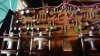
1576965051754890475996966664673.jpg Will check fully in morning, but look at the picture, q5 is second from left, ksc1845. Picture from a few posts ago. Could it be I have the in wrong orientation????
 
Last edited:
Is that to be done while -C48 is being probed by signal trace? Sorry just wanna make sure, i am assuming so.

Ground the + side of C24. Result? LOUD Buzzing
Ground the - side of C26. Result? No Buzz
Yes, and I posted the wrong transistor in post 130, I should have listed Q6 not Q5, sorry.
I believe Q6 is the transistor at the far left of your picture, by the edge of the pcb, and I think it is oriented correctly, but I cannot see it very well in the picture.
I believe the problem is right in that area.
 
Last edited:
Thats brilliant, thank you for your help.
Will i just start to replace the resistors in that area? And the electrolytic caps?
If you could list the parts i should change it would really help, as i have already changed the transistors twice, and some of the electrolytics.
I know i have asked a lot and i really do appreciate your help @merlynski and @petehall347 , i know you have been poring over the schematics and trying to troubleshoot this from afar and i want to make sure you know just how much i appreciate the help!
 

Attachments

  • 15770189954854452081726757530696.jpg
    15770189954854452081726757530696.jpg
    40.5 KB · Views: 12
Last edited:
Thats brilliant, thank you for your help.
Will i just start to replace the resistors in that area? And the electrolytic caps?
If you could list the parts i should change it would really help, as i have already changed the transistors twice, and some of the electrolytics.
I know i have asked a lot and i really do appreciate your help @merlynski and @petehall347 , i know you have been poring over the schematics and trying to troubleshoot this from afar and i want to make sure you know just how much i appreciate the help!
You are welcome.
For the resistors just unsolder one end, lift it up and measure it, no need to replace good components.
Look closely and measure the 20kHz variable resistor, look for bad solder connections and cracked traces in that area.
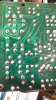
Would/can you post a high res close-up of the area around Q6 and the components from the foil side, the same area as the last post view of the top side, please.
 
Just so i am clear, i am going to focus my attention on lifting and measuring resistors in the area marked.
Is the area i have marked correct?
 

Attachments

  • tone control AOE.jpg
    tone control AOE.jpg
    118.2 KB · Views: 11
Ok so far i have tested all of the following, one leg lifted. All of which are bang on to spec give or take.
R62, R32, R30, R50, R52, R48, R16, R10, R14, R18, R28, R4, R2, R6, R8, R12.

Where the hell can i go next? R23, R25, R25, R26????
Do polystyrene caps ever fail, could i have shorted one of those giving the board a quick resolder, i.e. too much heat on the styrene caps??

At a complete loss now, was really hoping the culprit would be exposed.

Open to any and all suggestions, calling all AK'ers!!!
 
Last edited:
Back
Top Bottom