
PTL-Pioneer
Super Member
Negative on the ceramics, no change unfortunately. Mylars and polystrenes on order, thanks



@rcs16Well i guess you could
1) verify the bias voltages are close to what they have printed in the big schematic, supply is +/-24V gets dropped by R60 to around +/-13V
2) 2 tone amp sections sub,main are in series, could isolate it to the sub or main, could lift one leg of C16, (+ve lead connection to the 39K & 22K,) and bypass the sub wire directly to the R38,42 with C32 +ve leg lifted
test the pots too as said above and test the switch section S10a for resistance, power off of course

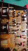
I am sticking to the left hand side of the board geographically speaking folks just to be sure i am in the correct area. I replaced the ceramics on this side of the board only, not the right hand side.
Is that to be done while -C48 is being probed by signal trace? Sorry just wanna make sure, i am assuming so.
Ground the + side of C24. Result? LOUD Buzzing
Ground the - side of C26. Result? No Buzz
The amps speaker selector should make no difference because it is way downstream from the tone controls, except you hear the buzz from the speakers.Ok so i think i may yet again have made a mistake.
I have switched the speakers selector to off when performing this test tone control activated.
Now when i use the signal tracer (powered computer speaker probe) and touch the +side of C24 - NO BUZZ. When i probe the negative side of C26 BUZZ
??? Have i been doing something wrong here? Should i have my speaker selector to a speaker or off?
I do apologize folks
Ok so i think i may yet again have made a mistake.
I have switched the speakers selector to off when performing this test tone control activated.
Now when i use the signal tracer (powered computer speaker probe) and touch the +side of C24 - NO BUZZ. When i probe the negative side of C26 BUZZ
??? Have i been doing something wrong here? Should i have my speaker selector to a speaker or off?
I do apologize folks, again! Hopefully this time will get it right. Speakers selector off, tone control engaged. all negative legs of caps tested using signal tracer.
C24 - No
C16 - No
C26 - Buzz
C14 - No
C42 - Buzz
C32 - Buzz
C40 - No
C48 - Buzz
OK, no buzz on C16 means the buzz is NOT coming into the tone circuit from before it (upstream). It is the input to the tone circuit.
No buzz on C24: that is a very low impedance point for ac signal because it feeds the base of the transistor (Q5 on page 37/38 of SM, GN schematic) so the signal tracer will not reproduce it, it is too small a voltage signal (buzz).
C26: Buzz, probably coming from Q5 collector as Q5 is a voltage gain amp circuit.
C14: Same explanation as C16, also C14 is the tone control bypass signal path when tone switch is "OFF."
C40: Same explanation as C24.
C42 and C32 are both downstream from the buzz source so will, of course, have buzz but are not part of the source UNLESS C50 is open/bad and the +13v supply line is part of the feedback path. Is there a buzz on the + of C50 (100µF, 16V)?
C48: output of tone circuit, buzz always there.
P.S. When I directed you to ground certain points during troubleshooting those points were carefully chosen to NOT destroy any components, just to kill the signal. Randomly grounding the wrong parts of the circuit will probably cause magic smoke to escape.
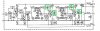
That is not the main schematic on pages 37/38 of the SM, It is the board schematic from page 44, note the component designations are different between the two. That had me confused earlier and I have used component designations from pages 37/38 since I noticed it and asked which you were using. This is an error in the SM. I have noticed Pioneer usually puts the left channel above the right channel on schematics but on page 44 the left channel is the lower one and the right channel is the upper one.View attachment 1719891
Caps with buzzing highlighted on schematic
OK, that tells me the source is in the area between C16 (no buzz) and C32 (buzz). Unsolder one end of C32 and leave it pulled up, then power up and see if the buzz is still present at the - of C26. Try to isolate the 'bad' amp stage.Is there a buzz on the + of C50 (100µF, 16V) - No Buzz