• The move to the new server is done. There are some software and database maintenance updates in process. This has us passing the hat around to help out. We appreciate any donations. Seriously, even a dollar helps. The payment page may be found here - https://www.audiokarma.org/support.html

SA8500 only works on DBT

I believe we have localized the problem area as the sub-tone section between C16 and C32. Is one end of C32 still unsoldered/lifted? If so, please lift one end of C16, this isolates that section from everything except +/- power and ground, then power up and check with the signal tracer at C26 to hear if that circuit is still buzzing. If so there is no point in looking at other areas that are not directly related to that circuit, it just creates more frustration.
Let me know what you find, I'll be around . . .
 
Last edited:
-C32 leg lifted and +C16 - Signal trace on C26 Dead Quiet Both Sides of this cap

I will replace all of the following except for the capacitors, and though i know the resistors tested good ill replace them too.
R24, R26,R28, R20, R22, R30, R32, R34, R36, C18, C20, C22.
C24, C26, C28, C30 and Q5.

Also the Sub Tone VRs: 'BASS 50 Hz' and 'Treble 20kHz'
Am i not testing these rotary pots correctly?
I will pull each, negative to wiper (Center) and positive to either left or right leg. Should see equal resistances for each increment either side of TDC (top dead center) position (so extreme left setting should have same resistance as extreme right setting)

These again are pretty darn expensive
 
Last edited:
I don't recommend replacing good parts 'just because', especially 'darn expensive ones', and you can introduce a problem you did not have before. Every time you solder, unsolder, move, or bend something you (or me or whoever) risk causing damage, so don't do any unnecessary rework.
You are measuring the VRs correctly as far as you have described.
Stepped resistor VRs are not the same as a continual resistance potentiometer with a sliding wiper, but rather are multi-step switches with fixed resistors between the switch positions.

So, if C26 no longer has a buzz with C16 AND C32 lifted we are making progress. Look at it like this: a change that causes the buzz to quit is valuable information and narrows down the problem. This is the first time the buzz is gone from a place it was always present before. Reconnect C32 and see if the buzz at C26 stays gone, but don't change anything else yet.
 
Last edited:
Thank you, i will do nothing more except the testing you have suggested, it will be tomorrow probably before i can get to it. I will report back on the results.
 
Thank you, i will do nothing more except the testing you have suggested, it will be tomorrow probably before i can get to it. I will report back on the results.
No problem with time, its your project and I am enjoying helping as I can :).
 
Review of past actions and results, please correct me if I am wrong:
Looking back at previous posts when C16 was connected there was buzz at C26 whether C32 was connected or not connected (Post 189). Then you disconnected C16 and that killed the buzz (Post 203) Now with C16 still disconnected and C32 reconnected we have buzz again on C26 (Post 208)?
 
I marked the three caps I think we have been looking at on the attached image, please confirm if we are talking about the same caps, C16, C26, C32.
IMG-20191111-WA0002marked.jpg
 
We are talking about the same caps yes, you gave them marked up beautifully.

I can repeat the testing if there are any inconsistencies, but yes I think that's the case, with c32 and c16 out of the circuit no buzz at C26. With c32 back in c26 buzzes.
 
IMG_0001arrowsmall.jpg
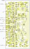
This is foil side of pcb from the SM page 43, I marked 4 spots with different colored arrows, red:C16+; dark blue:C26- ; R24: purple; R26:green.
Please measure the resistance between the red and dark blue points. Verify 0Ω between red and purple points, and 0Ω between dark blue and green points.
In order for a circuit to oscillate there has to be positive feedback between the input and the output, that is what I am looking for now.
 
70K OHM Between those points but take a while to get there, as in resistance slowly climbs and settles at value given
 
Last edited:
70K OHM Between those points but take a while to get there, as in resistance slowly climbs and settles at value given
That sounds like a cap charging up. C16 still disconnected? Are you touching the probes directly to the pcb pads?
How long does it take before it settles on 70K? Remove C16 (if not disconnected), C26 and C24, and remeasure, please. Does it still charge up slowly?
 
No, everything is reconnected. Takes like 10 seconds or more to settle. Reading taken from pad to pad, but pad has a component leg installed.

I will now Remove C16, C26 and C24, from the board completely and remeasure per the arrowed image
 
Help me to help you, please don't get ahead of me. This is a step by step process, if you reconnect things and I don't know it I can't make good troubleshooting choices. I an earlier post (#208 & #211) you said you reconnected C32 and the buzz came back, had you also reconnected C16 at the same time?
 
Back
Top Bottom