• Please note that Audiokarma will be offline briefly for updates early on Monday morning, September 28th.

SAE 2200 Rebuild

R59 and R60 which are the bias measuring points are 62 ohms. I am shooting for 1.1 to 1.2 volts across the 62 ohm resistors for bias, which is adjusted by the 500ohm trimpots on the output board. I have not had any issues getting the bias set.

R35 R36, R37, R38 are 68 ohms. I am of the understanding that the quiescent current is measured across these 68 ohm resistors (R35, R36, R37, R38). For the quiescent current I'm looking for about 1.0 to 1.2 volts across the 68 ohm resistors, this is adjusted by the value of the select resistors (R21, R22), and/or R27, R28, R29, R30 (150k or 180k).

It's not hard to get confused, do I have this right?

QC shoot for 1.0vdc, the rest above you wrote would be correct for QC.
 
R59 and R60 which are the bias measuring points are 62 ohms. I am shooting for 1.1 to 1.2 volts across the 62 ohm resistors for bias, which is adjusted by the 500ohm trimpots on the output board. I have not had any issues getting the bias set.

R35 R36, R37, R38 are 68 ohms. I am of the understanding that the quiescent current is measured across these 68 ohm resistors (R35, R36, R37, R38). For the quiescent current I'm looking for about 1.0 to 1.2 volts across the 68 ohm resistors, this is adjusted by the value of the select resistors (R21, R22), and/or R27, R28, R29, R30 (150k or 180k).

It's not hard to get confused, do I have this right?
For bias I did it by checking voltage at emitter resistor.
30ma for about 6mv across emitter resistor.
 
Have been away from the bench for a bit. I'm very close to completing this but I'm still having difficulty getting the QC and DC offset where I want it (or think it should be).

I replaced the 150k ohm (original value in this amp) R27/R29 and R28/R30 with 200k ohm, and switched the 2.0M trimmer to a 2.2M ohm fixed resistor in the "select" R 21/R22 position.

This brought the QC on ChA up to .97vDC and about .59vDC on ChB. If 1.0vDC is the goal, I'm pretty close to it on ChA, but not on ChB. The DC Offset is 1.5mV on ChA, and about 15-16 mV on ChB. Both channels are well within the +/- 50mV spec, but ChB is still 10x ChA. I have no problem adjusting the bias to about 1.2v on both channels, and measured distortion is very low on both channels.

Every component on the drive board is new, and matched across the channels. I would expect the channels to measure closer.

- I put a decade resistance box in series with R22 on ChB and dialed the value up from 2.2M to 3.2M with little impact on QC or DC offset.
- I could try increasing R28/R30 some more starting at 220k, but have not yet tried this.
- I even thought about swapping the differential pairs from the ChA to B to see if the specific set of transistors in ChA is "better" than what is in ChB. I did try to match the transistors within and across channels for hFE as best I could with an Atlas DCA55, so this swap seems like a shot in the dark.

It is "close enough" to declare victory, or are there more things to try to get ChB QC and DC offset to measure closer to ChA?
 
Channel A seems fine but B seems to have some issue going on. Did you change out the diodes on the board(s) and all the resistors too?
 
Last edited:
Yes, all resistors are 1% MF. Before replacing, checked every new resistor and measured, picked and matched them on a Fluke MM. If there were two per channel, I matched all four for a given position/value. The only parts on the PSU, drive, and output boards I did not replace were the coils on the output board, the relay, and the power transformer. I checked and matched every part before installation, resistors, capacitors and transistors. There should not be any differences channel to channel. I did not do a curve trace on the transistors, so there could be some differences, but I did check and match hFE.

But I agree with you - something - is causing ch B to behave differently.
 
The DC offset is OK in channel B but that QC is low. On the other hand I’ve seen from factory very large differences in the select resistor from channel A to B, way over 1Meg but you tried that without any real change.
I’ve had resistors that were new test out fine but when installed did not work.
Maybe try spot checking voltages on A vs B.
 
I don't see how it would cause the problem you are having, but I've read several times that carbonized circuit boards can begin to conduct like a resistor. I wonder what that might do to that trimpot circuit?
 
There was a failure (40 years ago) that led to burning on the output board, and failure of components on the driver board, but this only affected ChA, not ChB which is the one I can't get to co-operate. The boards were cleaned with IPA before installation of new components. Still a possible factor, but more likely that it would impact ChA not ChB.
 
I found the source of the problem. :jump:
When checking voltages to determine possible issues causing lower QC and higher DC offset on ChB, I found an unsoldered leg on the 2.2M resistor for ChA (R21). After soldering this leg, and with 200k resistors still in place for R27/29 and R28/R30, the measurements improved on ChB and were much closer across channels. QC was 0.82vDC on both channels, and DC offset was 12-13mV on ChA and 18-19mV on ChB. These were more like the results I was looking for.

To continue experimentation, I put a decade resistance in series with R21 (ChA select resistor) adding resistance in 100k steps up to a total of 3.3M, but was only able to get the QC to increase to about .87v. I removed the decade box, keeping the 2.2M on both channels. It does not seem that adding more resistance to R21/R22 is needed.

Next, I increased the value of R27/R29 (Ch A) from 200k to 220k. This brought the QC up to about .897 on ChA and .815 on ChB. Encouraged by these results, I went ahead and increased the value of the resistors on ChB (R28/R30) to 220k. This (final) change produced QC of .92 to.93 on ChA, and .91 to .92 on ChB, and DC offset of about 16mVDC on ChA, and 20mVDC on ChB. I then set the bias to 1.214 on both channels, and re-checked QC and DC offset, which did not measurably change. Happy with these results, I checked THD on both channels at 1kHz.
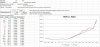
THD below 0.05% up to 10 watts, 0.1% or less up to 70 watts, and less than 0.2% to rated power of 100 watts. Distortion this low is pushing beyond the lower limits of my equipment. But these measurements tell me the amp is performing like it was designed to. Detailed distortion results attached.
 

Attachments

  • 2200 Distortion 20230306.JPG
    2200 Distortion 20230306.JPG
    77.3 KB · Views: 19
Last edited:
Yes, higher than what is called for on the schematic or Service Manual. Unfortunately there's no spec for this 2200.:(
 
I just checked my 3100 schematic, little brother amp, no voltages. Then checked the 2300 schematic, big brother amp, again no voltages. It seems this era of SAE amps is a bit lacking in the service info. Then I thought about the Son of Ampzilla, similar to the 2200, it's Q.C. is 51ma!! So that's a no go.
 
Craig,

It worked --- kinda.

I increased R27/29, and R28/30 from 220 to 330 ohm, and replaced the 2.2M fixed with the 2.0M trimmers I had in earlier, which gave me adjustable "select" (R21/R22) resistors. I had no problem dialing the QC in to 1.00 volts, BUT now the DC offset has gone up. It's 45mV on ChA and almost 50mV on ChB which is right at the published spec. Perhaps 330 ohms is too high.
 
The 2300 I have is showing voltages. 69.5 to 68.5 across the 68ohm resistor. That’s how I thought 1vdc might be good to go with.
 
Last edited:
The 62 ohm resistors are where I have been measuring bias. It is in the range of 1.2v.. You have 68 to 69 volts across these resistors? Sorry, I'm confused by this.

I have been measuring QC across the 68 ohm resistors (R35, R36, R37, R38) and getting roughly 0.8 to 1.0v depending on the combination of resistors I have in R27/29 and R28/30.
 
Back
Top Bottom