• The move to the new server is done. There are some software and database maintenance updates in process. This has us passing the hat around to help out. We appreciate any donations. Seriously, even a dollar helps. The payment page may be found here - https://www.audiokarma.org/support.html

SAE 2400L dc offset question along with recap, restoration tips and recommendations.

Burialcloud

New Member
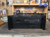
I bought a SAE 2400L this week for 350. It was in “working” order but I figured it would probably need an overhaul before use.
Got it on my bench today and channel B seems great. Was able to get the offset and quiescent dead on. (Don’t have a distortion analyzer to check bias unfortunately)

Channel A, however, wouldn’t get quite where it needed to be. DC on the outs stays around 540 mv or 1/2 a volt. When I adjust the trimmer it’ll jump down temporarily and then quickly level back up to .5v. Quiescent was way high when I first checked, brought it down to 1.7 on one resistor and 1.6 on the other. Again close but not within tolerance according to the service manual.

So, my questions. Sorry for all this. Is it likely these issues will be fixed by a simple recap/restore job and what all should I change? Should I spend the time taking all the output transistors off to clean everything and add new goop and those little heat shields. (And where does one find those little guys)

Does anyone have a general parts list or a guide for a general restore on one of these? I’m seriously considering buying the 185$ kit on eBay from hifiaudio.com but damn that’s $$$. They said they would have their listings back up asap so I got a few days to decide if I’m willing to dump that much. Any suggestions on if this is worth it? I checked the transistors temp on channel a’s preamp board to see if any were overly hot but they all were relatively similar and none were seemed super hot. Can just drifted caps and various other small parts be causing my offset issue or does it point to something more serious?

I saw a thread concerning the mod to get rid of thump when ya turn the unit off. Sorta followed it I think. Not sure if I’ll perform this mod. Is there any risk in not doing it or just the annoying thump? Cause that is something I can live with.

I believe I will replace the wires going to the rca jacks with some good canare. Stuff in there looked pretty thin and junky. Is that an ok idea? Should I do the same on the speaker wire?

Are these sprague caps across my speaker outputs stock or is this some sorta weird mod I should get rid off?

I wanna do this thing right and haven’t plugged it into a speaker yet as I wanna get it all dialed in first. This amp will be powering passive speakers/monitors in a studio/mixing setting. Clarity, soundstage, and reference quality are very important to me. I’ve been told a few times I should get a bryston and be done with it, but I’m a big SAE fan and have the entire 02 series for my home setup.

Will this serve me well or should I move it to my home gear and grab a bryston 4b like all the engineers keep telling me?

Thanks in advance for any help you can offer. I’ve done some work on non tube gear but I am still very much learning in general as I go. It seems a fine specimen to rebuild and enjoy.
 

Attachments

  • DAC5D845-3B3E-4D64-82F2-85865DE716AE.jpeg
    DAC5D845-3B3E-4D64-82F2-85865DE716AE.jpeg
    136 KB · Views: 47
  • 4D1A3B7B-4EE3-4213-9E19-A5EEC3051B1A.jpeg
    4D1A3B7B-4EE3-4213-9E19-A5EEC3051B1A.jpeg
    84.9 KB · Views: 45
Register to hide this ad
Yes the Sprague’s are stock.
The 1.6vdc was for home use, 1.7vdc for pro use.
It should serve well once fixed up.
I wouldn’t necessarily count on a recap to fix that DC offset issue. Those dual input transistors can be problematic.
The bias, 2.2vdc collector to collector of Q7 & Q8.
Have any pics of the input boards?
 
Last edited:
Looks like you have the older version of it before the toroidal transformer. I have it’s brother the 2400 with the meters that I need to do the input boards yet.
 
Looks like you have the older version of it before the toroidal transformer. I have it’s brother the 2400 with the meters that I need to do the input boards yet.
Is pre toroidal a good or bad thing? I’m gonna be in Denver through Sunday, but can add a pic of the input boards once I’m back. By dual inputs we’re talking the larger transistors on the sides of the preamp board correct? If I remember correctly there was 4 on each side of each preamp board. 1 green and 3 black.
And yea I read that about the quiescent setting in the manual. Since that side wouldn’t go to 1.6 for both I figured where I set it was at least safe. What exactly is meant by home and professional use? And which would I want in a studio setting for maximum clarity and least amount of coloration?
As far as checking bias using q7 and q8. I did read through a thread discussing that but was a little lost. The way you’ve laid it out seems quite easy. Thanks! I only got a quick look last night. But I don’t remember how easily marked the board is with codes. I can read a really basic schematic but the “schematic manual” I got off hifiengine was a bit beyond me.
Also what should I get for the channel b bias adjustment. I saw different things discussed like chopsticks whittled down, etc. I definitely don’t have any small screwdrivers that long.
Thanks for the guidance!
 
Please leave the wires, lets get it going first. It's not the caps. It's almost never the caps, why do you think it is?
Did you clean the trimmer with DeOxit? Replace the input pair? How much experience do you have?

SAE 2400L Repair | Audiokarma Home Audio Stereo Discussion Forums

Also the 02 series is....much worse than a Bryston 4B. This is getting closer.

Wires would definitely be a final thing after everything’s square.

My experience… I run a guitar repair shop and mainly fix guitars, pedals and tube amps. I have a pretty basic understanding of electronics but can usually figure my way through a tube amp repair and diagnosis. I have built guitar amps as well. My main amp for stage use is a soldano SLO clone I built. I am not very experienced with solid state electronics and amp sections. I’ve dabbled and fixed a few things with guidance on the web. But I find it much more confusing than tube amps. My close friend is an electronics engineer who builds and designs boards (has a guitar pedal company as a hobby and builds satellite boards for a big company as his day job) and usually he can help me when I’m super stuck. But he isn’t really familiar with older amps or diagnosis.

I did deoxit both the offset pots and the quiescent pots with the power off when I saw how touchy they were being. This didn’t help. Channel A would go down, jump around, and then drift back up to .540 or so within a matter of 10-20 seconds. Even with the pot turned all the way down. I’m sorry but by input pairs are you referring to the larger transistors along the side of each preamp board? Was hoping these were ok. Not sure how to source them and in the past I’ve had trouble figuring out modern equivalents for those types of transistors.

As far as caps, I didn’t necessarily think it was that, but wasn’t sure, which is why I asked. I sorta guessed it was a transistor. I’ve seen people saying even lifting them and cleaning them and using new thermal paste can fix small issues. How true is this? Should I try it? I’m not entirely sure how to test those transistors to be honest. Perhaps someone can guide me?

The restoration kit comes with all caps and a bunch of other small stuff but I don’t think it comes with any of the larger transistors. I’ll add a pic below of the one I’m gonna possibly grab. Maybe you can dissuade me? How easily can I source this stuff on my own? Seems like an undertaking but I suck at sourcing stuff. I assume a recap job is definitely in order either way for best results with the amp. Looks like this comes with an instruction set which would seem rather invaluable to me as someone very much learning. Not sure how much the large cans cost alone so maybe this isn’t even a bad deal at 185 or whatever it was.

As far as the 02. I’ve read lots of great things about the series. Lots of hate directed against the “two” but plenty of love for the 01 and 02. What don’t ya like? I quite like my home setup. Definitely the best thing I’ve ever had. Using 2 a502’s as monoblocks on each side.

link to recap kit. They told me it will be back up for sale asap. https://www.ebay.com/itm/1545765136...UztQmBRTAW&var=&widget_ver=artemis&media=COPY
 
Wires would definitely be a final thing after everything’s square.

My experience… I run a guitar repair shop and mainly fix guitars, pedals and tube amps. I have a pretty basic understanding of electronics but can usually figure my way through a tube amp repair and diagnosis. I have built guitar amps as well. My main amp for stage use is a soldano SLO clone I built. I am not very experienced with solid state electronics and amp sections. I’ve dabbled and fixed a few things with guidance on the web. But I find it much more confusing than tube amps. My close friend is an electronics engineer who builds and designs boards (has a guitar pedal company as a hobby and builds satellite boards for a big company as his day job) and usually he can help me when I’m super stuck. But he isn’t really familiar with older amps or diagnosis.

I did deoxit both the offset pots and the quiescent pots with the power off when I saw how touchy they were being. This didn’t help. Channel A would go down, jump around, and then drift back up to .540 or so within a matter of 10-20 seconds. Even with the pot turned all the way down. I’m sorry but by input pairs are you referring to the larger transistors along the side of each preamp board? Was hoping these were ok. Not sure how to source them and in the past I’ve had trouble figuring out modern equivalents for those types of transistors.

As far as caps, I didn’t necessarily think it was that, but wasn’t sure, which is why I asked. I sorta guessed it was a transistor. I’ve seen people saying even lifting them and cleaning them and using new thermal paste can fix small issues. How true is this? Should I try it? I’m not entirely sure how to test those transistors to be honest. Perhaps someone can guide me?

The restoration kit comes with all caps and a bunch of other small stuff but I don’t think it comes with any of the larger transistors. I’ll add a pic below of the one I’m gonna possibly grab. Maybe you can dissuade me? How easily can I source this stuff on my own? Seems like an undertaking but I suck at sourcing stuff. I assume a recap job is definitely in order either way for best results with the amp. Looks like this comes with an instruction set which would seem rather invaluable to me as someone very much learning. Not sure how much the large cans cost alone so maybe this isn’t even a bad deal at 185 or whatever it was.

As far as the 02. I’ve read lots of great things about the series. Lots of hate directed against the “two” but plenty of love for the 01 and 02. What don’t ya like? I quite like my home setup. Definitely the best thing I’ve ever had. Using 2 a502’s as monoblocks on each side.

link to recap kit. They told me it will be back up for sale asap. https://www.ebay.com/itm/1545765136...UztQmBRTAW&var=&widget_ver=artemis&media=COPY
Sounds like you can tear something down and solder pretty well, so let's get this show on the road.

Ok sounds good. We need to replace some transistors then. Input pair - the transistors at the input of the amp. Study the schematic on this guy. It's on HiFi Engine. Transistors subs are easy, we'll give you P/N's. Please read through the thread I linked.

No, leave them be, it's not true.

Don't get the kit. I will personally make a cart at Digikey and share it with you.

They're just not nearly as good as the early stuff.
 
Sounds like you can tear something down and solder pretty well, so let's get this show on the road.

Ok sounds good. We need to replace some transistors then. Input pair - the transistors at the input of the amp. Study the schematic on this guy. It's on HiFi Engine. Transistors subs are easy, we'll give you P/N's. Please read through the thread I linked.

No, leave them be, it's not true.

Don't get the kit. I will personally make a cart at Digikey and share it with you.

They're just not nearly as good as the early stuff.

Awesome! I’ll try to study the schematic and similar threads while I’m out of town. I’m not great at reading schems. With guitar amps I can almost always find a pcb layout as a reference to help guide me through the schematic and to find which parts I’m looking at. I apologize in advance for being green. But yes I sling solder everyday in some form and actually love this challenging stuff more than fixing guitars for the most part.
I may have to take some pics with silly arrows pointing around to confirm stuff. But I very much appreciate the help. I’ll be in touch probably Monday evening once I’m back and have it on my bench.
Last thing. This is just a pic I lifted from the web but I added some arrows, are these the transistors we’re talking about. The other board on the opposite side of the amp is the one I can’t get to bias correctly but I assume they are identical. So are these the input transistors? Or are those actually on the backside of the board?
Thanks again.
 

Attachments

  • 4F96D178-A621-4A73-B6A6-BD327EEE58FA.jpeg
    4F96D178-A621-4A73-B6A6-BD327EEE58FA.jpeg
    92.4 KB · Views: 33
Is pre toroidal a good or bad thing? I’m gonna be in Denver through Sunday, but can add a pic of the input boards once I’m back. By dual inputs we’re talking the larger transistors on the sides of the preamp board correct? If I remember correctly there was 4 on each side of each preamp board. 1 green and 3 black.
And yea I read that about the quiescent setting in the manual. Since that side wouldn’t go to 1.6 for both I figured where I set it was at least safe. What exactly is meant by home and professional use? And which would I want in a studio setting for maximum clarity and least amount of coloration?
As far as checking bias using q7 and q8. I did read through a thread discussing that but was a little lost. The way you’ve laid it out seems quite easy. Thanks! I only got a quick look last night. But I don’t remember how easily marked the board is with codes. I can read a really basic schematic but the “schematic manual” I got off hifiengine was a bit beyond me.
Also what should I get for the channel b bias adjustment. I saw different things discussed like chopsticks whittled down, etc. I definitely don’t have any small screwdrivers that long.
Thanks for the guidance!
No not those. Q1& Q2.
 
Awesome! I’ll try to study the schematic and similar threads while I’m out of town. I’m not great at reading schems. With guitar amps I can almost always find a pcb layout as a reference to help guide me through the schematic and to find which parts I’m looking at. I apologize in advance for being green. But yes I sling solder everyday in some form and actually love this challenging stuff more than fixing guitars for the most part.
I may have to take some pics with silly arrows pointing around to confirm stuff. But I very much appreciate the help. I’ll be in touch probably Monday evening once I’m back and have it on my bench.
Last thing. This is just a pic I lifted from the web but I added some arrows, are these the transistors we’re talking about. The other board on the opposite side of the amp is the one I can’t get to bias correctly but I assume they are identical. So are these the input transistors? Or are those actually on the backside of the board?
Thanks again.
No.
Right to the left of those middle caps is the one the other is probably being blocked by the wire in the pic.
 
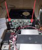
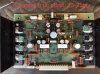
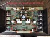
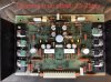
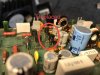
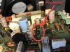
29E2654A-DAC5-498B-8AD5-A8022D842360.jpeg Sorry for the delay on this. Finally got it open again last night. Lots of pics below.

I took both preamp boards out and carefully examined and thoroughly cleaned them. The board that was having the dc offset problem is within tolerance after a cleanup. I basically reflowed solder that had already been reflowed previously and removed any bad rosin crud between solder points. There was quite a bit. Also used deoxit d5 on all wiring harnesses and heavily flushed the quiescent and dc offset pots.

That side now stays around dc offset 15-25mv with the pot cranked down to absolute minimum. However, this is well under the 50mv mentioned in the service manual as being within tolerance, so I assume I’m good? The other channel is between 0-10mv dc offset and has plenty of range left to go further.
Quiescent on both sides is around 1.65 as per the manual and within tolerance.
The side that was originally not cooperating has had some solder reflowed and at least two parts updated.

Can anyone explain to me what is meant by “home/1.6v” vs “professional/1.7v” setting for the quiescent? Since this will be used in a studio setting and clarity and a flatter response is most important… do I want professional? What change in sound can I expect from 1.6-1.7 and is a compromise in the middle a good idea?

last question. One side of the big silver output transistors on the heat sink are marked “Toshiba” while the other side is labeled “sae”. Will that affect overall performance?are the Toshibas likely replacements and is that the best choice?

I lied, one more question. Still not sure where to check the bias. Above it says to check emitters on q7 and q8 for the bias of 2.2. Can someone point out to me where I should be checking. My board doesn’t seem to have the schem codes screen printed on it.
 

Attachments

  • 1E780E02-4EAE-4032-AD98-97FDB8C6B7B3.jpeg
    1E780E02-4EAE-4032-AD98-97FDB8C6B7B3.jpeg
    143.1 KB · Views: 26
  • 75A730F4-442C-4F32-A6CC-4A2428206B44.jpeg
    75A730F4-442C-4F32-A6CC-4A2428206B44.jpeg
    149.3 KB · Views: 27
  • 89B04182-B688-4A22-B091-3754CD039C30.jpeg
    89B04182-B688-4A22-B091-3754CD039C30.jpeg
    169.7 KB · Views: 28
  • C0F0470D-FADB-4ECE-8E09-8B83FEA1F9D7.jpeg
    C0F0470D-FADB-4ECE-8E09-8B83FEA1F9D7.jpeg
    96.1 KB · Views: 29
  • 50E7EAC3-E9D4-4C44-933A-9F966ADCBAC7.jpeg
    50E7EAC3-E9D4-4C44-933A-9F966ADCBAC7.jpeg
    101.8 KB · Views: 28
  • 643821E7-A27E-4AB6-B72F-28D58BED903D.jpeg
    643821E7-A27E-4AB6-B72F-28D58BED903D.jpeg
    41.5 KB · Views: 25
  • 98C85640-1FA1-491B-8207-1C795BEEA74A.jpeg
    98C85640-1FA1-491B-8207-1C795BEEA74A.jpeg
    48.5 KB · Views: 24
The quiescent current level, the 1.6-1.7V, and the output stage bias work together to reach the .03-.04% distortion described in the manual. If used Professionally you would assume the output will be running at constant higher Watts so the output stage bias will be set lower, less heat, and the quiescent a bit higher and still reach the distortion spec. Home use is just the opposite, run the output stage a bit hotter and the quiescent current lower and still get to the distortion spec.

The DC offset on the high channel will probably just get worse over time, replace the four input differential transistors with matched pairs and you should be able get the trim pot. very close to the center of adjustment.

Look at the construction of the output transistors especially where the cap meets the base, do they look the same? If so they are probably all Toshibas.

Craig
 
Thanks!
Sounds like I want the quiescent at 1.6 then. This will be used mostly at lower volumes for critical listening/mixing.

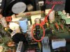
I have no idea which are the “4 differential input transistors”. Would you be able to use my pics and circle them? Are they included in the ones that have had the two replaced?
I’m used to circuit boards I work on saying “r1 and c1 and t1 etc. under each component” and this doesn’t give that type of layout guidance so I’m having trouble here. As I mentioned I’m not able to read these schems, far beyond me, and I’m not super familiar with a standard solid state circuit.

Ivandezande up above you said you would you be able to help me with a digikey cart. Is that still possible? Totally lost on what to buy. And should I only concern myself with those input differentials or is there anything else?

Last thing, I’m still lost on which one is q1 and q2 to check/adjust the bias. If someone could use the above photos and put and arrow or something on those I’d be very grateful.

Thanks again!
 
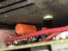
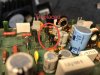
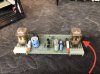
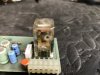
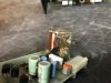
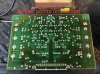
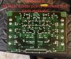
Oh also, I pulled the little board with the big relays. One of the relays looks like it could have been damaged but maybe it’s supposed to be like this? One of them seems to have a tiny little hole and the brass tab inside is bent outward in an L shape where that hole is. Is this normal? See pics below. FB8644F5-4977-4DD4-B440-A74B2C6875CA.jpeg B85684A7-4549-4FF5-A47E-18EBE98D1976.jpeg 82224682-0FA5-4358-808B-E9765583858B.jpeg 098A2123-F67D-4497-BC78-903ECE12CCEE.jpeg
 
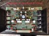
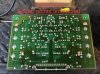
Also, I’m reattaching the photos again from before of the preamp boards. I can’t tell if I added them right the first time.060AF1E3-5307-416D-948C-0E05230C35CB.jpeg 0DA45F84-A905-45C1-A6EA-1D6919AC4E95.jpeg F1BCD839-6E21-4258-8A98-F5885EF5FC69.jpeg C768A75D-5B4A-4EDD-B5D5-17678F36DF16.jpeg 1A544EAE-3FD5-4EC5-B3D1-CAB9BC8B073B.jpeg 05F50FAC-88A3-4A92-87E4-0C6B008DC4F7.jpeg
 
You have circled the negative pair, the positive pair is on the opposite side of the board, next to the gray capacitors. The board is symmetrical, + circuitry is on the right side and the - circuitry is on the left. The 2N5087 are the PNPs on the - side. The 2N5210s will be the ones to replace on the + side. They need to be matched for best results. I just use the hFE tester on a cheap Rat Shack DMM and usually end up the trimmer in the middle or close to it. I recently started using the 2N5210/2N5087 pair from Central Semi, I bought 100 of each from Mouser and have to test very few to get 4 matched pairs.

That relay is kaput, replace both. Some early units had a real oddball pinout, at least nowadays. Post picture of the solder side of the relay board.
 
Thanks!
Sounds like I want the quiescent at 1.6 then. This will be used mostly at lower volumes for critical listening/mixing.

I have no idea which are the “4 differential input transistors”. Would you be able to use my pics and circle them? Are they included in the ones that have had the two replaced?
I’m used to circuit boards I work on saying “r1 and c1 and t1 etc. under each component” and this doesn’t give that type of layout guidance so I’m having trouble here. As I mentioned I’m not able to read these schems, far beyond me, and I’m not super familiar with a standard solid state circuit.

Ivandezande up above you said you would you be able to help me with a digikey cart. Is that still possible? Totally lost on what to buy. And should I only concern myself with those input differentials or is there anything else?

Last thing, I’m still lost on which one is q1 and q2 to check/adjust the bias. If someone could use the above photos and put and arrow or something on those I’d be very grateful.

Thanks again!

Printed on the board BC237B(Q1) & BC307B(Q2).
 
You have circled the negative pair, the positive pair is on the opposite side of the board, next to the gray capacitors. The board is symmetrical, + circuitry is on the right side and the - circuitry is on the left. The 2N5087 are the PNPs on the - side. The 2N5210s will be the ones to replace on the + side. They need to be matched for best results. I just use the hFE tester on a cheap Rat Shack DMM and usually end up the trimmer in the middle or close to it. I recently started using the 2N5210/2N5087 pair from Central Semi, I bought 100 of each from Mouser and have to test very few to get 4 matched pairs.

That relay is kaput, replace both. Some early units had a real oddball pinout, at least nowadays. Post picture of the solder side of the relay board.
Probably have some good gain readings from those I would think.
 
Those BC #s are obsolete though you can still find them. The Central Semi 2Nxxxx have an average hFE of 400 or so.
 
Back
Top Bottom