• The move to the new server is done. There are some software and database maintenance updates in process. This has us passing the hat around to help out. We appreciate any donations. Seriously, even a dollar helps. The payment page may be found here - https://www.audiokarma.org/support.html

Sansui 1000A Receiver - Dim Bulb Test Burns Bright

Zekeman

AK Subscriber
Subscriber
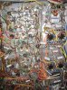
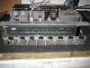
I have a Sansui 1000A tube receiver which appears to be all original. Plugged it into my dim bulb tester and it burns bright. There is no output. Stereo light illuminates, dial lights come on. It appeared that no tubes began to glow. No smoke.

I have never done anything to tube amps before. Can anyone with experience with this model shed light on any obvious causes or things to look for?

Thanks.
 

Attachments
  • 2010-07-23 001.jpg
    2010-07-23 001.jpg
    105.2 KB · Views: 94
  • 2010-07-23 007.jpg
    2010-07-23 007.jpg
    149.7 KB · Views: 68
  • 2010-07-23 002.jpg
    2010-07-23 002.jpg
    141.9 KB · Views: 58
  • 2010-07-23 005.jpg
    2010-07-23 005.jpg
    147.8 KB · Views: 61
  • 2010-07-23 010.jpg
    2010-07-23 010.jpg
    56 KB · Views: 74
Last edited:
Register to hide this ad
Pull the power tubes and test 'em if you can. If not, try inserting one pair at a time. Do you have a multimeter?
 
Yes I do have a multimeter. I am not sure which are the power tubes can you ID?
 
Last edited:
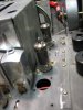
The big ones in the rear, between the xfmrs. I think they're 7591's, without checking the service literature. That appears to be a VERY fine specimen, by the way. Some of the transformer potting has apparently melted and run under the chassis, but it's unlikely to be a trouble indication. What wattage lamp are you using in the dimbulb fixture?
 
Oh the output tubes......OK They are 7591's. I will report back. I have a 100 watt bulb in the tester.
 
Last edited:
Sounds like a dead short on the power transformer, HV rectifier, or first stage P/S capacitor to me.

Does the 1000A have a solid state rectifier? I've got one sitting downstairs, but I cannot remember (and I am far too lazy to go look).
 
I pulled the power tubes and still glows. I pulled all the tubes I was able to (those not in a metal enclosure) and it glows then fades.
 
Sounds like a dead short on the power transformer, HV rectifier, or first stage P/S capacitor to me.

Does the 1000A have a solid state rectifier? I've got one sitting downstairs, but I cannot remember (and I am far too lazy to go look).

dont know about the solid state rectifier...High voltage rectifier? (what do they look like)? "P/S" power supply cap as in main filter cap?
 
Last edited:
I discounted the probability of a dead short because you said the lamps lit up. Now I'm not so sure. I think the next step is to cool it down and check for shorted rectifiers, especially the main B+ doubler diodes connected to the 180V winding. There's a good schematic in the AK Database. Be safe and check for high voltage first!

Hold on... The dimbulb glows, then fades? Maybe it's better to start plugging tubes back in. Perhaps you've got a short in one of the small tubes.
 
Last edited:
Great I appreciate your input .....and ....I need to proceed slowly as I have only worked on solid state up to now....I need to start by identifying what the rectifier diodes actually look like under this thing....I should maybe post a video of just how it behaves and then we can proceed............Could I pull all the tubes possible and then powwer it up and start to plug in one tube at a time to determine if its a tube issue? Or should I just recap the entire underside and then begin with a set of fresh caps knowing they are good?
 
Last edited:
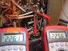
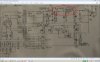
I tested ~250 volts at what I believe to be the giant 600 ohm resistors in the pics and diagram attached...(it actually read up to 250V and then started to come back down so in the pic it read 225V)


========================

This evening I decided to set my multimeter for continuity test and connected the black lead to the receivers chassis and the red lead to the point circled on the (right-most) picture in Blue (I used previously taken picture).....this white wire comes from the power transformer. The meter indicates continuity which means the main power transformer could be shorted???? ...but then I tested this process on a known-good solid state receiver and there was continuity as well on a couple of leads.

Thanks
 

Attachments

  • 2010-07-24 001.jpg
    2010-07-24 001.jpg
    96.8 KB · Views: 49
  • 1000A 1.jpg
    1000A 1.jpg
    60.3 KB · Views: 37
  • Power Point.jpg
    Power Point.jpg
    43.2 KB · Views: 31
Last edited:
225VDC is about right if your AC line input voltage is about half of normal. The schematic gives 478VDC with nominal line voltage and loading. How about checking DC voltages further on down the power distribution chain, and on that -19V preamp supply and the output tube grids (pin 6)?
 
The dim bulb tester has some limitations. One is tube amps due to the loading of the filament. As a quick check, disconnect one of the filament leads coming out of the xfmr. The bulb should barely light under this condition.
 
Thanks Gents....I have replaced a few caps and have the others on order....I'll take your advice once I install the new components.
 
Good going so far, check HV with meter for safety.

Keep in mind that without the tubes, there will be little load to drain off the high Voltages and you may get zapped!

Check the circuit with the meter before "going in"!

BTW, the diodes look like black plastic "M&M" candies and should be replaced (the 1000A has a SS supply).

Please read all you can on HV safety, we want to talk WITH you, not ABOUT you!:yes:

Mark T.:music:
 
...I have replaced a few caps and have the others on order....I'll take your advice once I install the new components.

I don't like the shotgun approach to repair. I prefer to identify the problem and make the unit functional, then do the preventive maintenance. If you install all new caps and still have troubles, then you don't know whether the new cap is the problem or something else.
 
Replaced all caps (except the big cans and power filter caps) and the two rectifiers on the supply caps. Fired it up...tubes glow, CD on....music!!

The tuner works but the right channel out in everything but FM Stereo. Overall sounds good.

Issue...The one output transformer is noticeably warmer than the other....:scratch2:
 
The tuner works but the right channel out in everything but FM Stereo. Overall sounds good.

Issue...The one output transformer is noticeably warmer than the other....:scratch2:

Both channels play in FM stereo mode only? That has to be a switching problem. If you've already used contact treatment, try following the signal path through the switches with an ohmmeter.

Compare output tube currents by measuring voltage drop between center tap and anode connections of the OPTs, or insert 1-ohm precision resistors in the cathode connections if you want the most reliable information.
 
If OP tube currents are balanced.

Check the OP stage currents first before deciding that the below situation is the cause.:yes:

It is normal to have the "center-most" OP transformer run warmer than the one at the end as the center one is flanked by 4 OP tubes, the end one has only 2 nearby, being black colored, the transformers CAN absorb heat from the nearby tubes (I put aluminum foil on the sides that face the tubes).

Fan cooling is recommended for this set, put a fan(s) at the rear, and "suck" out the hot air near the OP tubes, use a slightly larger fan for the OP tubes near the power transformer, as this side gets hotter due to the 2 power resistors located there.:scratch2:

You may also consider taking off the metal shield behind the power transformer and drilling some 1/4" holes in it near the location of the above power resistors, you MUST retain it in place to keep the power transformer heat from cooking the 2 capacitors behind it.:yes:

Hope this helps!:thmbsp:

Mark T.:music:
 
Back
Top Bottom