• The move to the new server is done. There are some software and database maintenance updates in process. This has us passing the hat around to help out. We appreciate any donations. Seriously, even a dollar helps. The payment page may be found here - https://www.audiokarma.org/support.html

SANSUI 2000 - Dead Right Channel

Don't get distracted

Words to live by, thanks for the reminder!

I guess you can't amass over 20K messages if you're giving bunk advice, ha! You did it again, Dr. Audio, it was totally C804. I did just as you said, looking at signal on both sides, and it was clear that the cap had failed. I didn't have any 5uF caps but assumed a 4.7 would suffice, popped it in and am now listening to this beautiful rig. THANK YOU!

Lastly, since I now have a much better idea of this troubleshooting sequence, for signal tracing, is it best to start with the driver board and work backwards from there? Always keen on establishing the best method so thanks in advance for confirming.

Bob, Larry and Conrad, thank you all as well for jumping in. I have massive respect for you all and sincerely appreciate your generosity in helping noobs like myself, cheers!

UPDATE:

Should have let the unit completely warm up before taking a victory lap. Right channel is working well now but at zero volume I'm getting some intermittent snap crackle pop. Although I'm tempted to simply recap the driver board(s) what do you advise specific to eliminating this lingering issue?
 
Last edited:
It's probably a small signal transistor on the power board, but first guesses are often wrong. I like to give 'em a quick shot of freeze mist and see if the problem gets better or worse.
 
Thanks, Conrad, I'll check it out.

Not sure if this helps at all, but when I power the unit down there's lingering sound/static on that right channel for a few seconds while the left channel is quiet - does that help determine where in the signal path the issue might be?
 
Also, as a reference, is there any harm in replacing the caps with slightly different uF values? I'd used a 4.7 uF to replace a 5 uF cap at C804 and I'm considering replacing more, so, for instance, the main filter caps, they're 2000 uF but I only have some 2200's. Any issue as long as I'm close?

The unit is sounding strong but the more I listen to it the more I hear some high end noise, pretty airy sounding, would be nice to eliminate some of that along with tracking down whatever's making that intermittent static sound on the right channel.

Thanks again for the coaching, much appreciated.
 
Nobody makes a 5uF cap anymore, 4.7uF is a standard value, use that. Usually it's ok to use a slightly higher capacitance value or any voltage above the original.
If you don't know or understand how the cap is used in the circuit, it's best to use the closest value you can get.
Troubleshooting:
You can start in the preamp and work towards the output or start at the output and work back, just be consistent and don't jump around.
Regarding your noise, since it gets the noise with the volume control down, the problem is probably in the amp. Since there was one bad cap and the unit is over 40 years old it would be prudent to replace all the electrolytic caps in the amp section, then see if that fixes it. If it doesn't fix it, get a can of freeze spray and spray a small amount on each of the small transistors in the amp. The one that causes the noise is bad.
Glad I could help.
 
  • Like
Reactions: JB8
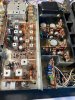
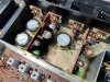
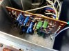
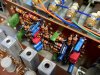
Quick update. In an effort to eliminate the noise, I recapped the driver boards first with no significant change other than the sound tightening up some. The values were ~20-30% over spec so obviously beneficial, but the noise remained, so I shifted to the tone board where I replaced the transistors one pair at a time, checking for change between each swap (freeze spray revealed no culprits). Sound continued to get better but still had some low volume transient bursts of static and a persistent high frequency air/hiss. Next up, EQ amp board (F-1037). Recapped that dude and jimminy crickets the cap values were all at least double the spec, for C603/C613 (should be 30uF) they tested at 114uF and 70uF respectively, wowzers. This bit of work made a huge difference and now the unit is considerably quieter at idle with volume at zero. I also recapped the FM Stereo Indicator board since it was so easy to get to. Can't say the other boards were as easy, fairly awkward in fact but worth the effort. I understand the 2000X tone board is easier to access, but again, just have to be patient and careful to mark capacitor or transistor pinout orientation and it can be done.

Very impressed with this old dude, a couple years younger than me but now has a new lease on life and sounds very different, in my opinion, then any other unit/brand I've had the pleasure to work on.

Lastly, this specific thread taught me more about troubleshooting than I expected it to, very thankful. I have a feeling this won't be my last Sansui, I'm hooked!

IMG_1094.jpg
 
Hey Leahysailor, thanks for sharing, I've had the same kind of thing happen with switches/buttons, you just never know what it will end up being.

Btw, your profile pic represents one of the greatest moments in Masters history, in my opinion, love it.
 
Yes I agree one of the most moving things to ever happen at Augusta. showing respect to the course was amazing. When Ben Crenshaw won right after Harvey Pennick passed and broke down on 18 was another. I always love that Crenshaw had the same caddie he always had at the Masters. It used to be a requirement that the players use the courses Caddies.
 
  • Like
Reactions: JB8
Pumping the brakes again, feels like I'm close to the finish line, but need some additional coaching specific to adjusting bias.

After my last update I still had some lingering noise, slight, but annoying. I hadn't fully recapped the tone board, so after essentially recapping the entire unit, including the tone, EQ, driver boards, filter & ripple caps, along with new transistors throughout including new output transistors, the unit is incredibly quiet and has little to no perceptible noise, so I wanted to check DC balance and adjust bias. First time with this unit so I'm not going to muck around, going slow, asking for help.

(Btw, for those wondering, ALL cap values had drifted anywhere from 30% to 300%, so they were all due for a refresh. Plus, I sincerely enjoy the process.)

After consulting the service manual and multiple threads, I've got a dummy load attached on both speaker A terminals (some crappy 6 ohm speakers with a 4.7 ohm resister added in series to get to roughly 10 ohms per what the manual referred to), fuses removed, AUX function, volume at zero, balance centered. If I take a reading across the empty fuse holder I'm getting a stunning 70V DC. Once I got this reading I turned the unit off right away after checking to see if it was on both channels, and it was.

Are VR-802/804 capable of reducing the voltage enough to get me down to 25 mA's? Again, didn't want to screw anything up since I'm so close, and coaching here is much appreciated.

IMG_1103.jpg IMG_1104.jpg IMG_1105.jpg IMG_1106.jpg IMG_1107.jpg
 
Last edited:
You need to set your dmm to milli amp scale (ma). Be sure you have the probe leads in the correct sockets in the meter and meter set to measure ma or will probably pop the meter fuse. using mini grabbers attach to each side of the fuse holder with the fuse removed. should see about 25ma of current. Ask first before proceeding if unsure :)
 
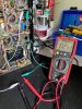
Thanks, Overunder1, I appreciate your guidance! I jumped back in tonight, per your instructions - DMM set up correctly this time - and got roughly 114 mA on both channels... Adjusting VR802/404 didn't change anything so perhaps they're faulty? When testing ohms across them without powering up the unit I'm getting 205 ohms on VR-802 and 165 on VR-804, but neither change at all when adjusted.

I know Larry and Conrad suggest replacing the open pots so they may just be open, happy to swap them out if necessary, will just need to order a handful of them.

Any tips on confirming they've pooped out? And if we feel they're shot, any advice on a proper replacement? They're big ones, ha!
 
Last edited:
Doubtful both potentiometers failed---
Were you possibly measuring incorrectly, those values look to be across the ends and not the end to wiper.
When you were measuring the bias did you have the speaker switch on (may need that load on a cap coupled design)
If you were indeed getting 114 ma of current that would be evident with rapidly heating heat sinks around the output transistors
 
Ladies and gentlemen, just as a reminder, the score is officially Overunder1 with 2 points, JB8 0 points... Man, that darn wiper. Sometimes I wonder how I'm capable of doing any of this stuff, wow. o_O

Measuring end to wiper both pots reacted to adjustment, power off, using DMM in ohms setting.

Specific to the DMM testing mode, I'm confident my meter is in the correct position, but I also thought Waterworld was a great movie, so I could be wrong.

IMG_1109.jpg

Previous to testing the bias I'd been checking output transistor temps before and after I'd replaced them and there were no issues with elevated temps. Old output transistors were in the mid to upper 90 degrees range, new ones are in the mid 80's F.

I am, however not sure about the load I'm using (may not be the primary issue but worth more discussion).

In the manual it says to apply a 10 ohm resistor (1W) to the speaker terminals. When I search for dummy loads most appear to be pretty elaborate, so I'm assuming you can't just use and actual 10 ohm resistor across the +/- terminals on each channel. The throw-away speakers I have are only 6 ohm, so I inserted a 4.7 1/2W resistor in series on the neg. speaker terminal, so maybe that's the issue. Seemed like a good idea, but this is the same guy who's struggling to test a variable resistor, ha! If I test across the speaker terminals I'm getting essentially that 10 ohm resistance, but maybe this unconventional approach is creating an issue.

I'd previously taken a different pair of small, 4 ohm speakers, and daisy chained them to get to an 8 ohm load (7.7 to be precise), then used them to set bias on a different unit one channel at a time.

IMG_1110.jpg

At any rate, I'm sure this is all user error, happy to try some other methods and I appreciate the help.

Lastly, and perhaps this is the most puzzling bit, when I have the DMM on with this set up, no power, I'm getting 25 mA on one channel, 22 mA on the other. I'd watched a YouTube video of a 2000X bias adjustment and the power had been applied during testing, so I'm assuming the power needs to be on, but since my track record is not trending upwards I'm keen to double check my approach. :)

IMG_1112.jpg
 
Overundr1 for the win!

Dialed both channels in at 25 mA, easy peasy when you have things set up correctly, thanks for catching my multiple mistakes, all of which were 100% avoidable if I'd just taken the time to read the manual.

Although I know it's never intended, this forum never ceases to humble me. The level of detail, thoroughness of research, patience, diligence and common sense required to do this work continues to be exemplified by the experts here. I take a baby step forward and two adult steps backwards on every project, this one, however, has really been impactful, and sincerely appreciated.

Thanks again!
 
Last edited:
Добрий день я з України. Купив собі цей чудовий ресивер. Скажіть будь ласка чим можна замінити транзистор 2SA-537. Які аналоги можна поставити?
 
Back
Top Bottom