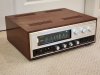
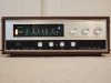
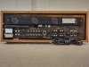
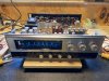
I’m finishing up a Sansui 3000A and thought I’d share my notes/observations since I had a hard time finding a concise summary of the issues & solutions for this beautiful sounding receiver. My unit isn’t particularly pristine but does have the wood case so I figured it would be a fun project – that was before I ended up spending 25+ hours on it. In the end, it was worth it and I’d do it again – especially now that I know what to do on the next one – but it was an interesting journey. My thoughts in no particular order:
- Factory Mods
o My receiver already had the factory mod with output caps installed, but whomever did the mod, neglected to replace the SM150 diodes – might be what killed mine as two of them were failed open. I replaced all of those with 1N4004s since that’s what I had on hand, but most have used 1N4002s. Mine also had 3A fuses installed instead of the recommended 2A fuses, so I changed those out – AGX fuses are required. These are 1” x ¼” - slightly shorter than standard 1 ¼” x ¼” (30 x 6mm) fuses.
- Output Transistors
o Bendix B-170007s were replaced with OnSemi MJ21194Gs. 3 were shorted C-E.
- Pre Power Board – TRZ-2D
o Replaced all 2SC756 transistors (2 were shorted) with KSC2690A transistors. I soldered leads to the 2690As and ran them over the top of the board to the foil side. I mounted them to the original heat sinks with some thermal compound using the top screw and the leads oriented up.
o Replaced the bias trimmers with 200Ω, 18 turn, 500mW top adjusting trimmers. I soldered on lead extenders to allow for proper installation and angled them for easy adjustment.
o Tested the carbon comp resistors – mine were all spot on so none needed to be replaced.
o Replaced the 4 - 800Ω, 5W, 10% resistors with 1% Vishays. 3 measured around 780Ω but one was 720Ω (low end of the spec) and showed obvious signs of high heat.
- Driver Amp Board – TRD-6B
o Replaced 2SC696 transistors with KSC2690A Transistors. Similar mounting with the Pre Power board but the leads were bent 90 degrees up and the wires were run to the foil side through holes that are conveniently located near the heat sinks.
o Replaced C801 & C808. C801 had ESR in the 100’s of ohms. C808 was OK but replaced. The rest of the capacitors tested good for ESR and capacitance was in spec (I’m not a blanket recap fan – replace as necessary. Flame away, lol).
o R806 (27k) had been replaced by someone with a 22kΩ resistor. Corrected that. R810 and R820 (6.8kΩ) had been clipped out and replaced by a 10k paralleled with a 22kΩ on the foil side of the board. Corrected that.
o TR801 & TR803 (2SC858 - R145 package on my board) were replaced with KSC1815s
- Bias and DC Offset Adjustment
o Do this on a DBT first – I used a 100W bulb – then on direct line voltage once you are sure everything is stable and warmed up.
o I’ve read a few accounts of how to do this but here’s what worked for me.
§ Use 2 DMMs in mA mode across the L (R) fuse clips – fuses removed, of course (L = F001 & F002, R = F003 & F004).
§ Use a 3rd DMM connected between R016 (R018) and ground to measure DC offset. Clip onto the terminal strip side of the resistor, not the transistor emitter side.
§ Now the fun part - simultaneously adjust VR801 & VR802 (VR803 & VR804) until you get 80 mA on both DMMs with as close to 0 V as you can get on the DC offset. Changes to one VR will affect both mA readings and the DC offset reading. This is important because you can achieve 80ma on both lines with DC offset way out if you don’t monitor it as you adjust. Not sure how you’d do this with just one or even 2 meters.
§ With the fuses out, the filter caps won’t discharge, so be careful putting the fuses back in or discharge them before you do it . . .
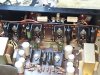
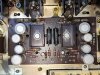
- TRZ-2D & TRD-6B Before:
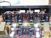
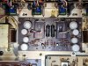
- TRZ-2D & TRD-6B After:
- Control Amp Board – TRM-3A
o TR701, 3, 5, 7 (2SC693 - R145 package) replaced with KSC1845s
o TR702,4,6,8 (2SC536 – R145 package) replaced with KSC1815s
o C706 & C725 were way out and the leads were corroded. C716, C717, C735 & C736 were also bad and most of the others were marginal, so I replaced all of them.
o C708 & C727 were replaced with film caps. They are Suzuki PIO caps that have a bad reputation although these tested fine. - EDIT - the original Suzuki caps are rated at 400V. They see a fraction of that, so I used 100V film caps if memory serves - that's what i had on hand.
o Resistors are all carbon film and tested OK.
- All Other boards
o Transistors, caps and CC resistors tested and replaced as needed. I don’t have any noise through the phono section, so I left the transistors alone.
- Misc
o Replaced the Suzuki 0.005uF PIO caps on the fuse board with 0.0047uF film capacitors
o Replaced the 0.033uF power switch snubber and the 0.0047uF line filter caps with XY safety caps of the same value.
- Volume Potentiometer (2 x 250kΩ audio taper w/loudness taps)
o After I rebuilt the amplifier section, the receiver sounded great, but at zero volume, output was quite high and only a few degrees increase on the volume pot produced an unacceptably high volume level.
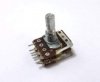
o The bad caps on the control amp board were the primary cause of this, but while troubleshooting, I discovered that the 250kΩ dual volume pot measured 118 ~120kΩ out of circuit on each section – half what it should be. Found a 250k dual pot with loudness tap that looked like it might work and was able to install it without too much trouble aside from some PIA soldering of all the wires/components connected to it. The shaft is a little shorter than the original and the spline was a tight fit to the knob, but it worked. It’s still not clear to me how a pot loses resistance, but I’ll tear it apart at some point to figure it out.
- Protector lamp
o This is a 25V, 0.09A in an E10 base. I’ve seen these mistakenly replaced with 8V LEDs and it doesn’t end well. I fitted a 28V, 0.1A wedge base lamp into an E10 base to replace it. There are probably more elegant solutions but that’s what I had on-hand and it works well. All the other lamps were replaced with LEDs.
- Tuner Alignment
o The service manual lays out the procedure well – I’m still deciding if I want to do this. I have the equipment and have done several, but this tuner sounds pretty good so I probably won’t mess with it unless I run into issues. Just replaced questionable caps and cleaned the variable tuning cap for now.
I’ll try to remember to post a photo when it’s all back together.
Rich
- Factory Mods
o My receiver already had the factory mod with output caps installed, but whomever did the mod, neglected to replace the SM150 diodes – might be what killed mine as two of them were failed open. I replaced all of those with 1N4004s since that’s what I had on hand, but most have used 1N4002s. Mine also had 3A fuses installed instead of the recommended 2A fuses, so I changed those out – AGX fuses are required. These are 1” x ¼” - slightly shorter than standard 1 ¼” x ¼” (30 x 6mm) fuses.
- Output Transistors
o Bendix B-170007s were replaced with OnSemi MJ21194Gs. 3 were shorted C-E.
- Pre Power Board – TRZ-2D
o Replaced all 2SC756 transistors (2 were shorted) with KSC2690A transistors. I soldered leads to the 2690As and ran them over the top of the board to the foil side. I mounted them to the original heat sinks with some thermal compound using the top screw and the leads oriented up.
o Replaced the bias trimmers with 200Ω, 18 turn, 500mW top adjusting trimmers. I soldered on lead extenders to allow for proper installation and angled them for easy adjustment.
o Tested the carbon comp resistors – mine were all spot on so none needed to be replaced.
o Replaced the 4 - 800Ω, 5W, 10% resistors with 1% Vishays. 3 measured around 780Ω but one was 720Ω (low end of the spec) and showed obvious signs of high heat.
- Driver Amp Board – TRD-6B
o Replaced 2SC696 transistors with KSC2690A Transistors. Similar mounting with the Pre Power board but the leads were bent 90 degrees up and the wires were run to the foil side through holes that are conveniently located near the heat sinks.
o Replaced C801 & C808. C801 had ESR in the 100’s of ohms. C808 was OK but replaced. The rest of the capacitors tested good for ESR and capacitance was in spec (I’m not a blanket recap fan – replace as necessary. Flame away, lol).
o R806 (27k) had been replaced by someone with a 22kΩ resistor. Corrected that. R810 and R820 (6.8kΩ) had been clipped out and replaced by a 10k paralleled with a 22kΩ on the foil side of the board. Corrected that.
o TR801 & TR803 (2SC858 - R145 package on my board) were replaced with KSC1815s
- Bias and DC Offset Adjustment
o Do this on a DBT first – I used a 100W bulb – then on direct line voltage once you are sure everything is stable and warmed up.
o I’ve read a few accounts of how to do this but here’s what worked for me.
§ Use 2 DMMs in mA mode across the L (R) fuse clips – fuses removed, of course (L = F001 & F002, R = F003 & F004).
§ Use a 3rd DMM connected between R016 (R018) and ground to measure DC offset. Clip onto the terminal strip side of the resistor, not the transistor emitter side.
§ Now the fun part - simultaneously adjust VR801 & VR802 (VR803 & VR804) until you get 80 mA on both DMMs with as close to 0 V as you can get on the DC offset. Changes to one VR will affect both mA readings and the DC offset reading. This is important because you can achieve 80ma on both lines with DC offset way out if you don’t monitor it as you adjust. Not sure how you’d do this with just one or even 2 meters.
§ With the fuses out, the filter caps won’t discharge, so be careful putting the fuses back in or discharge them before you do it . . .
- TRZ-2D & TRD-6B Before:
- TRZ-2D & TRD-6B After:
- Control Amp Board – TRM-3A
o TR701, 3, 5, 7 (2SC693 - R145 package) replaced with KSC1845s
o TR702,4,6,8 (2SC536 – R145 package) replaced with KSC1815s
o C706 & C725 were way out and the leads were corroded. C716, C717, C735 & C736 were also bad and most of the others were marginal, so I replaced all of them.
o C708 & C727 were replaced with film caps. They are Suzuki PIO caps that have a bad reputation although these tested fine. - EDIT - the original Suzuki caps are rated at 400V. They see a fraction of that, so I used 100V film caps if memory serves - that's what i had on hand.
o Resistors are all carbon film and tested OK.
- All Other boards
o Transistors, caps and CC resistors tested and replaced as needed. I don’t have any noise through the phono section, so I left the transistors alone.
- Misc
o Replaced the Suzuki 0.005uF PIO caps on the fuse board with 0.0047uF film capacitors
o Replaced the 0.033uF power switch snubber and the 0.0047uF line filter caps with XY safety caps of the same value.
- Volume Potentiometer (2 x 250kΩ audio taper w/loudness taps)
o After I rebuilt the amplifier section, the receiver sounded great, but at zero volume, output was quite high and only a few degrees increase on the volume pot produced an unacceptably high volume level.
o The bad caps on the control amp board were the primary cause of this, but while troubleshooting, I discovered that the 250kΩ dual volume pot measured 118 ~120kΩ out of circuit on each section – half what it should be. Found a 250k dual pot with loudness tap that looked like it might work and was able to install it without too much trouble aside from some PIA soldering of all the wires/components connected to it. The shaft is a little shorter than the original and the spline was a tight fit to the knob, but it worked. It’s still not clear to me how a pot loses resistance, but I’ll tear it apart at some point to figure it out.
- Protector lamp
o This is a 25V, 0.09A in an E10 base. I’ve seen these mistakenly replaced with 8V LEDs and it doesn’t end well. I fitted a 28V, 0.1A wedge base lamp into an E10 base to replace it. There are probably more elegant solutions but that’s what I had on-hand and it works well. All the other lamps were replaced with LEDs.
- Tuner Alignment
o The service manual lays out the procedure well – I’m still deciding if I want to do this. I have the equipment and have done several, but this tuner sounds pretty good so I probably won’t mess with it unless I run into issues. Just replaced questionable caps and cleaned the variable tuning cap for now.
I’ll try to remember to post a photo when it’s all back together.
Rich
Last edited: