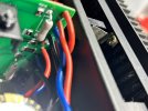
On mine as well, I measure 75 volts into each board.I am tempted to just remove these boards and resort back to the 1040 boards as I just don't know what else it could be. Voltage readings seem right leading to the boards.
Last edited:


On mine as well, I measure 75 volts into each board.I am tempted to just remove these boards and resort back to the 1040 boards as I just don't know what else it could be. Voltage readings seem right leading to the boards.

Ya I hear ya. I have been doing that since I have other projects. My voltage readings going into board seem right so I suspect something is going on with the boards even though they are brand new.I understand the frustration. Rather than reverting, removing yourself from the task for a few days may help clear the mind to make room for a solution.

Ya I think I can just fix these boards but want to wait for Bonzoro to reply back and see what he thinks. I mean no blame on his boards and not sure if it was wiring or what but I don't mind just fixing the issue at this point.Probably easier to fix the faulty 6013 board, than to reinstall and properly mod the 1040 boards. The latter can be made to operate reliably, but since you already have the 6013 boards, I'd stick with those. I'm wondering now if the one board was damaged due to screwy wiring?
2,3,4 then 6,7,8 go to output transistors. Pin 5 goes to filter. Pin 1 - fuse. Pin 12 tied to Pin 1.Cannot see from the pictures, do the wires from point 6,7,8 go to the output transistor wired to the output coupling capacitor?
Appreciate it.Will get a picture of my installation later this evening to compare with yours.


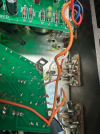
2,3,4 then 6,7,8 go to output transistors. Pin 5 goes to filter. Pin 1 - fuse. Pin 12 tied to Pin 1.
Took a reading from speaker terminals with no speakers and have almost 10v DC so something is not right.
I am having not dissimilar issues however, I was measuring bias on mine and when I put the fuses back in I saw, out of my peripheral vision, a little flash somewhere in the vicinity of R815 on each board (The receiver was not powered on but it was plugged in). I have a functioning L channel but it doesn’t sound quite right. The right challenge was out. Today I pulled all the outputs just to double check them and when I powered up the receiver again I had a slight distorted right channel and then it slowly faded out to zero output.
I have 75 watts on the cans of the outputs on the one side of each channel but the other cans show about 9 V or 12 V (for a left channel ) is the highest I can dial it up to. The right channel has millivolt readings. So I am watching this thread closely as it may provide clues into my unit.
Thanks.
Thank you for this. I have it wired just like that as well. I had pin 1, 12 connected but I am going to revert back to having 12 with power from DC on board F-1042. Then run a jumper from 12 to the other 12 just like how it was done originally on my F-1040 board.Note that pin 5 and pin 6 are linked together, I used pin 5
from front to back 1,2,3,4,5,6,7,8
pin 1 orange wire from fuse, also jumper to 12 (though on the 5000x you could use the other point as discussed)
pin 2 orange wire to output transistor that does NOT go to output cap
pin 3 grey wire to output transistor that does NOT go to output cap
pin 4 white wire to output transistor that does NOT go to output cap
pin 5 or 6 orange wire to output transistor that DOES go to output cap
pin 7 grey wire to output transistor that DOES go to output cap
pin 8 white wire to output transistor that DOES go to output cap
the other channel same way except colors are red/blue/black.
the wire running along the bottom of the board is the tie between pins 1 and 12
View attachment 3071860
View attachment 3071861