• The move to the new server is done. There are some software and database maintenance updates in process. This has us passing the hat around to help out. We appreciate any donations. Seriously, even a dollar helps. The payment page may be found here - https://www.audiokarma.org/support.html

Sansui 6060 -- issue, need help

DanielSpokan

New Member
Hello,
I have a Sansui 6060 that was my dad's growing up. It's an amp that we've used for a lot over the years and love it (both for the sound and the memories).

However, recently I have some problems with it. What it does is this: when I push the power button and turn it on instead of hearing a "click" shortly after the power button is engaged and the sound turns on, instead I hear nothing and the sound does not turn on. Occasionally after waiting a little bit I hear the "click" (which I assume is a relay) and then the sound works fine. But increasingly I do not hear the "click" and there is no sound.
Any one ever run into this? Any ideas on how to diagnose and fix?

I've done a fair amount with guitar tube amps, but never with receivers which seem a fair amount more complicated.

Any help would be very much appreciated. I have VOM and Oscope if needed.

Thank you!
Daniel
 
Register to hide this ad
No green protection light on the 6060.

If you are so inclined, you could test the DC at the relay.

Also, check the fuse resistors. Not sure how many there are in this one.

Rob
 
You and your dad have been enjoying this 6060 for more than 40 years. That illustrates the unbelievable quality of this equipment but it also indicates it's due for some attention. At a minimum it needs to be cleaned and serviced. It could be as simple as an adjustment or changing a few very cheap resistors.

- Pete
 
Thanks for the responses. Yes, Sansui must be built right to last so well... and yes, I think it's probably well past time to do some service. I'm going to check with my Dad to see if he did any servicing before he gave it to me.

Regrading the protection circuit... I looked over the schematic and did my best to locate the relay (sorry for my ignorance if I'm not looking at the right area). See attached. I posted this question on diyaudio too and one person mentioned checking the bias circuit. I was thinking I would start by checking to make sure each of the spots located in the attached schematic have the same voltage. If so, what should that voltage be? The capacitor says 50V; but the orange highlighted portion on the schematic (which is very hard to read) I believe says 37V. I assume I should check to make sure both are at 37V. If not then replace C519 and C520?

Do you think I should replace the Relay as well?... or just start with caps?
 
You have identified the relay but the power supply is not the issue. What is likely happening is the output voltage to the speakers has too much DC voltage. The primary function of the protection circuit is to monitor the amount of DC in the output and disconnect the speakers if it gets too high. Search for "DC offset" to learn more. It's adjustable if it's just a little off. The procedure is in the service manual.

Since it works sometimes, you can check and monitor it at the speaker terminals. With the unit on and the relay engauged, volume at zero, there should be close to zero DC volts at the speaker terminals. Does your multimeter have a min/max function? If so you can monitor the DC voltage while playing the receiver. Look to see what the meter captures when the relay clicks off.

This would also be a good time to build a dim bulb tester if you don't already have one.

- Pete
 
You have identified the relay but the power supply is not the issue. What is likely happening is the output voltage to the speakers has too much DC voltage. The primary function of the protection circuit is to monitor the amount of DC in the output and disconnect the speakers if it gets too high. Search for "DC offset" to learn more. It's adjustable if it's just a little off. The procedure is in the service manual.

Since it works sometimes, you can check and monitor it at the speaker terminals. With the unit on and the relay engauged, volume at zero, there should be close to zero DC volts at the speaker terminals. Does your multimeter have a min/max function? If so you can monitor the DC voltage while playing the receiver. Look to see what the meter captures when the relay clicks off.

This would also be a good time to build a dim bulb tester if you don't already have one.

- Pete

Thanks, very helpful. I googled dim bulb tester. Looks like a great idea. I will build one tonight.

Regarding DC offset, I did a little reading on this. Seems somewhat complicated... but maybe boils down to the waveform gets offset by a set amount of DC. That sound correct? In other words instead of just an AC wave alternating around 0V... there is now DC plus an AC wave?

I looked through the manual and found a procedure for adjusting the bias current. That was the only one that sounded similar to what you were saying. Is that the correct procedure? Attached are the results. The values seemed to keep going up and didn't stabilized completely... but I wrote out roughly where it seemed to stabilize. It looks like it is definitely out of spec. Should I adjusted the VR01 and VR02 to get it within spec? Do you think this could be what's wrong? Seems weird that it went out of spec. When/if the relay clicks, the amp sounds great despite being out of spec.
 

Attachments

The bias current and DC offset are two completely different factors with different procedures. DC offset is measured in millivolts at the speaker terminals. No 'scope needed. The bias current procedure in the service manual sets the bias current by measuring the voltage drop across the emitter resistors. There are separate trimmers for adjusting bias current and DC offset for both channels, a total of 4 trimmers.

You need a 'scope to measure DC balance in cap coupled amps. In this amp design, DC is filtered out of the output signal by passing that signal through a capacitor so you can't measure it at the speaker terminals. Your 6060 is not cap coupled, there is no DC filter on the output, The production relay protects the speakers if DC voltage gets too high.

- Pete
 
I should have looked before I spoke. The 6060 doesn't have a DC offset adjustment, just bias current. It may not be adjustable but it can still be too high. Measure the voltage across the speaker terminals with the volume at zero.

- Pete
 
I should have looked before I spoke. The 6060 doesn't have a DC offset adjustment, just bias current. It may not be adjustable but it can still be too high. Measure the voltage across the speaker terminals with the volume at zero.

- Pete

The DC voltage from the red speaker to the black speaker terminal for each channel measures 0.0V DC.

By the way, I have an Oscope and could use it for measurements if you think that would help. It is a digital scope so I can email you screen shots too.
 
It shouldn't be 0.0v. That what you see when both probes are on ground. It was probably in protection mode when you took that measurement. To see the actual DC voltage you need to measure it at a point before the relay. Look at the F-2648 board. There should be two copper coils, one for each channel. R09 and R10 are wired in parallel to those coils. Measure the voltage between chassis ground and each of those resistors.

On the driver board, F-2647 there should be four 220 ohm fuseable resistors, R31,32,33,34. It's likely they have drifted out of range and need to be replaced. Use metal film resistors.

- Pete
 
So when measuring between the two speaker terminals there should be DC voltage present?
There's near 0V DC across the speaker terminals under normal conditions as described earlier (vol. down, AUX, etc...). It's never really absolute zero and usually fluctuates between a few negative or positive (typically single digit) millivolts. Unfortunately, when the protection circuit protects, the speakers are disconnected and there's confusing absolute 0V DC again for no output at all. You have to bypass the protection circuit to know the real DC level that it 'sees'.
 
There's near 0V DC across the speaker terminals under normal conditions as described earlier (vol. down, AUX, etc...). It's never really absolute zero and usually fluctuates between a few negative or positive (typically single digit) millivolts. Unfortunately, when the protection circuit protects, the speakers are disconnected and there's confusing absolute 0V DC again for no output at all. You have to bypass the protection circuit to know the real DC level that it 'sees'.
To clarify: do NOT bypass the protection circuit. Rather, measure the voltage at the output of the amplifier circuit before the speaker relay.
 
Please help, I am a new member and am having a similar issue with my 6060. I would really appreciate your help. I have been able to set the bias for both channels to exactly 15 mv
I have replaced all transistors and capacitors and fusistors on the 2700 and 2701 boards. And the relay as well. Still in protection mode.
any suggestions from you wise ones on what I can check next?
 
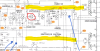
@D Chas - look at the replies above for detailed explanations, but you could have either 1) DC offset or 2) a defective protect circuit. The DC offset can be measured at the outputs of L and R channels (before the relay), but it may be easier to measure the two channels as they feed into the protect circuit. If those aren't engaging the protect function, you could have some bad components in the protect circuit itself. When NOT in protect mode, the protect circuit should be driving the coils of the protect relay. If you measure full voltage, the relay should be engaged. If I understand the operation of the protect circuit, the transistor in the attached schematic should be off (Voltage from base to emitter < 0.6volts). If either output (highlighted in yellow) has too high a voltage, this transistor will keep the relay turned off. You can easily check the voltage across the coil (i.e. the power supply voltage feeding the protect circuit) to be sure it is the correct value (it's hard to read in the image, but it looks like 27V to my eyes - this is on the right/coil side of the 220 ohm resistor. Let us know what you find.

Screenshot 2023-06-01 093346.png
 
@D Chas, protection circuits are rarely defective. We need to know the DC Offset voltage. If it's too high the protection circuit will prevent the speaker relay from turning on. Near the relay there should be two copper coils of wire. Each will have a resistor in parallel, R09 and R10. Measure the voltage the DC voltage between each of these resistors and chassis ground.

- Pete
 
Pete, thanks for checking back. On my board the resistors next to the coils are R05 and R06. a 2701 board. Without the driver board I measure 7v on R05 and 6.5 on R06. I installed the 2647 driver board and I measured 35v on R05 and .04v on R06.
 
That's your problem. That voltage should be very close to zero especially with the driver board out. Odds are your output transistors are blown.

- Pete
 
Back
Top Bottom