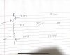
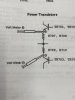
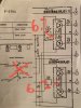
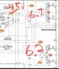
@D Chas - look at the replies above for detailed explanations, but you could have either 1) DC offset or 2) a defective protect circuit. The DC offset can be measured at the outputs of L and R channels (before the relay), but it may be easier to measure the two channels as they feed into the protect circuit. If those aren't engaging the protect function, you could have some bad components in the protect circuit itself. When NOT in protect mode, the protect circuit should be driving the coils of the protect relay. If you measure full voltage, the relay should be engaged. If I understand the operation of the protect circuit, the transistor in the attached schematic should be off (Voltage from base to emitter < 0.6volts). If either output (highlighted in yellow) has too high a voltage, this transistor will keep the relay turned off. You can easily check the voltage across the coil (i.e. the power supply voltage feeding the protect circuit) to be sure it is the correct value (it's hard to read in the image, but it looks like 27V to my eyes - this is on the right/coil side of the 220 ohm resistor. Let us know what you find.
View attachment 2900397
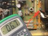
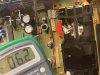
Jeff, it’s 43 v at where zd602 and R606 meet.@D Chas - look at the replies above for detailed explanations, but you could have either 1) DC offset or 2) a defective protect circuit. The DC offset can be measured at the outputs of L and R channels (before the relay), but it may be easier to measure the two channels as they feed into the protect circuit. If those aren't engaging the protect function, you could have some bad components in the protect circuit itself. When NOT in protect mode, the protect circuit should be driving the coils of the protect relay. If you measure full voltage, the relay should be engaged. If I understand the operation of the protect circuit, the transistor in the attached schematic should be off (Voltage from base to emitter < 0.6volts). If either output (highlighted in yellow) has too high a voltage, this transistor will keep the relay turned off. You can easily check the voltage across the coil (i.e. the power supply voltage feeding the protect circuit) to be sure it is the correct value (it's hard to read in the image, but it looks like 27V to my eyes - this is on the right/coil side of the 220 ohm resistor. Let us know what you find.
View attachment 2900397
Funny thing though, I’ve noticed that my R606 is actually a 1K ohm. Schematic says 220. My R604 is 220k.