• The move to the new server is done. There are some software and database maintenance updates in process. This has us passing the hat around to help out. We appreciate any donations. Seriously, even a dollar helps. The payment page may be found here - https://www.audiokarma.org/support.html

Sansui 6060 no sound both channels

drkilla

New Member
Hello there,
Got a Sansui 6060 with the 2700-2701 board, suddenly stopped working.
I have F-602 and F-603 fuses blown tried to replace them and they immediatly blow.
I have already replaced TR-602 and TR-603 but no changes
The relay sometimes clicks sometimes don't. And when speakers connected there is a sound when powering on.
Thanks
 
Register to hide this ad
Welcome.

Blowing those fuses points to a serious problem. The first thing you need to do is read about and build a dim bulb tester. Search here or YouTube or Google about a Dim Bulb Tester. The device will potentially save you from frying components and if used properly allow you to safely test the unit while you track down the short.

Those fuses are for the main amplifier power supply, when those fuse(s) blow the typical cause is one or more shorted output transistors. It could also be a shorted diode in the rectifier bridge or a shorted filter capacitor. If you know how to test the output transistors for shorts that would be the first place I would start. You can do quick go/no go test without taking them out of the receiver.

It would help us help you if we knew more about your skill level and the test equipment you have.
 
Welcome.

Blowing those fuses points to a serious problem. The first thing you need to do is read about and build a dim bulb tester. Search here or YouTube or Google about a Dim Bulb Tester. The device will potentially save you from frying components and if used properly allow you to safely test the unit while you track down the short.

Those fuses are for the main amplifier power supply, when those fuse(s) blow the typical cause is one or more shorted output transistors. It could also be a shorted diode in the rectifier bridge or a shorted filter capacitor. If you know how to test the output transistors for shorts that would be the first place I would start. You can do quick go/no go test without taking them out of the receiver.

It would help us help you if we knew more about your skill level and the test equipment you have.
Thank for your reply !
Yes I think that would be a good idea to build a DBT.
I’ll check the output transistors. Haven’t tested the diodes yet.
I suspect thoses fuse resistors, on DMM I got like 1ohm, but there is another resistances on the back of the pcb I don’t see them on the schema is it common?
I would say my skill level is basic/mid. And for the equipment only have a DMM and of course soldering iron.
 

Attachments

  • IMG_5741.jpeg
    IMG_5741.jpeg
    83.3 KB · Views: 18
Thank for your reply !
Yes I think that would be a good idea to build a DBT.
I’ll check the output transistors. Haven’t tested the diodes yet.

I suspect thoses fuse resistors, on DMM I got like 1ohm, but there is another resistances on the back of the pcb I don’t see them on the schema is it common?
ANY fuse resistor in equipment this old is suspect. For general long term well being most people just replace them even if they check OK. There are several in the 6060.
Fuse resistors generally soft fail by going high in value. They can be replaced with a metal film resistor of the correct value and rating.

A lot of meters have trouble correctly dealing with low ohm values. What does you meter display if you just short the leads together?

Pictures of the back of the board showing the extra parts would help. It is somewhat unusual but not unheard of for parts to placed on the back of the board

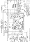
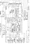
From your initial description I'm not sure why you are in the low voltage supply? F602, 603 are in the main amplifier power supply. (Blue Box)

6060a.jpg

Transistors TR-602 and 603 are in the protect circuit. What led you to replace them? (Green box)

Check R612 and R 618.

Please don't connect any speakers to the unit until you have confirmed proper operation.
 
Last edited:
Speaking of fuse resistors that can cause problems. Check R31 through R34 on the F-2647 driver board. They could cause a failure of the output transistors.

Again even if they check OK they should be replaced.

6060b.jpg
 
Make sense for the resistors, will replace them for sure.
If i short the leads together it says : OL and Bips
I will provide the pictures of the back as soon i'm back home.

Capture d’écran du 2024-08-22 14-26-32.pngCapture d’écran du 2024-08-22 14-26-32.png
Looks like we have not the same schema am I wrong ?
For the transistors someone told me that they can fail at some point so i replaced them to be sure.
 
Well they seemed OK but will replace them as well !
Seemed ok? Visual inspection or did you measure them? If they measure up to spec then It's up to you whether or not they are replaced, there is plenty of evidence that says they are likely to fail at some point. A failure does not necessarily mean it is open. The typical failure mode is for them to dramatically increase in value which throws the operating points of the circuit all out of whack.
 
Seemed ok? Visual inspection or did you measure them? If they measure up to spec then It's up to you whether or not they are replaced, there is plenty of evidence that says they are likely to fail at some point. A failure does not necessarily mean it is open. The typical failure mode is for them to dramatically increase in value which throws the operating points of the circuit all out of whack.
I did measure them, but i don't trust my DMM will try with another one.
The typical failure mode is for them to dramatically increase in value which throws the operating points of the circuit all out of whack.
Did not know about that.
Thanks for your patience ! it's the first time i try to troubleshoot that kind of issue.
 
Make sense for the resistors, will replace them for sure.
If i short the leads together it says : OL and Bips
I will provide the pictures of the back as soon i'm back home.

View attachment 3279510View attachment 3279510
Looks like we have not the same schema am I wrong ?
For the transistors someone told me that they can fail at some point so i replaced them to be sure.
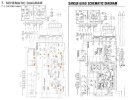
The answer would be it looks like we are not using the same schematic. There are two versions. Does yours have the F2701 and F2700 boards, or is it the single F2648 as I have been showing?

6060c.jpg

Once we have that straightened out we can be literally on the same page. The information remains valid for both.
 
The answer would be it looks like we are not using the same schematic. There are two versions. Does yours have the F2701 and F2700 boards, or is it the single F2648 as I have been showing?

View attachment 3279526

Once we have that straightened out we can be literally on the same page. The information remains valid for both.
I have the version with the F-2701/2700 board, sorry thought I mentionned that.
 
Hello again here is the back of the the board with the extra resistors.
I ended up change the resistors R613 and R612
Also checked the resistors on the driver circuit board, they are all toast. So I changed them.
I don't know if its helps but I've also checked the BIAS and it's in specs around 15mV. But the measurement is not stable but ends around 15mV.
Any recomendations ?
 

Attachments

  • IMG_5742.JPG
    IMG_5742.JPG
    155.5 KB · Views: 9
Hello again here is the back of the the board with the extra resistors.
I ended up change the resistors R613 and R612
Also checked the resistors on the driver circuit board, they are all toast. So I changed them.
I don't know if its helps but I've also checked the BIAS and it's in specs around 15mV. But the measurement is not stable but ends around 15mV.
Any recomendations ?
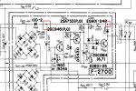
My service manual does not have the board layout for F-2701 board. Are those resistors on the bottom in the same place as R612 & 613 on the top?

If so then the original R612 & 613 might have failed at some point and instead of replacing them they just stuck new ones on the bottom. Did you check the ones you pulled out, that might answer the question.

If the bottom ones are indeed across the new R612, 613 you installed go ahead and remove them.

Now that you have done all this do you get a relay click every time you power on?

The bias will normally move around a little until the component temps warm up a bit. As long as it is ending up around 15mV after 10-20 minutes it is good.

Also just curious when you said the driver board resistors were "toast" what exactly does that mean? They were open or just a high resistance?
 
Last edited:
My service manual does not have the board layout for F-2701 board. Are those resistors on the bottom in the same place as R612 & 613 on the top?
I've attached the file. From my understanding they seems to be on top of the board, they physically are.

If so then the original R612 & 613 might have failed at some point and instead of replacing them they just stuck new ones on the bottom. Did you check the ones you pulled out, that might answer the question.
They failed, got 1 ohms on reading, already took off the ones on the bottom side and they're open.

Now that you have done all this do you get a relay click every time you power on?
Not every time, and it clicks strangely I mean the click is less audible than usual, Is there any chance that the relay has a problem ?

Also just curious when you said the driver board resistors were "toast" what exactly does that mean? They were open or just a high resistance?
On one channel got high resistance while on the other channel they are both open.
 

Attachments

  • sansui6060_2701.png
    sansui6060_2701.png
    335.4 KB · Views: 11
Even though it does not have an adjustment for offset you should check it and see what it is.
DC millavolts plus lead in the plus speaker out and minus to the chassis. Check left and right channels.

The relay not sounding normal could be the voltage for the protect circuit. All of these voltages are with the relay closed
Check it at the + end of C610 around +37 volts. (Cathode end of D609)
At the junction of R606 and ZD602 around +24 volts (Cathode end of ZD602)
While you are there the voltage at the Anode end of ZD602


6060f.jpg
 
Even though it does not have an adjustment for offset you should check it and see what it is.
DC millavolts plus lead in the plus speaker out and minus to the chassis. Check left and right channels.

The relay not sounding normal could be the voltage for the protect circuit. All of these voltages are with the relay closed
Check it at the + end of C610 around +37 volts. (Cathode end of D609)
At the junction of R606 and ZD602 around +24 volts (Cathode end of ZD602)
While you are there the voltage at the Anode end of ZD602


View attachment 3280745
IMG_5745.JPGIMG_5744.JPGIMG_5747.JPGIMG_5746.JPG
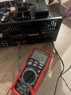
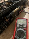
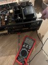
Here are the measurement of the DC offset
Check it at the + end of C610 around +37 volts. (Cathode end of D609)
At the junction of R606 and ZD602 around +24 volts (Cathode end of ZD602)
While you are there the voltage at the Anode end of ZD602
For thoses got OL everywere. Look like there is no power here or it's normal ?
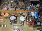
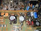
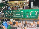
Here is the board if it can help

IMG_5750.JPG
IMG_5749.JPG
 
Last edited:
Here are the measurement of the DC offset.

Not crazy high, not great but should not cause the issue.

Check it at the + end of C610 around +37 volts. (Cathode end of D609)
At the junction of R606 and ZD602 around +24 volts (Cathode end of ZD602)
While you are there the voltage at the Anode end of ZD602
For thoses got OL everywere. Look like there is no power here or it's normal ?
Here is the board if it can help

IMG_5750.JPG
IMG_5749.JPG

How did you have the meter set? Looking to measure DC volt at these points.
Where was the ground lead attached?
Assuming you had the power on.
It should have close to the voltages I indicated.
 
How did you have the meter set? Looking to measure DC volt at these points.
The measurements with the pictures of the meter are all for DC offset, and the meter (not auto-ranging) was set to 200mV DC. It didn't seem like the PSU voltages you requested were measured. :dunno:
 
Last edited:
The measurements with the pictures of the meter are all for DC offset, and the meter (not auto-ranging) was set to 200mV DC. It didn't seem like the PSU voltages were measured. :dunno:
It seems he said they all read O/L, which is why I asked about the settings. If it was set on 200mV it would certainly read O/L :eek:

Check it at the + end of C610 around +37 volts. (Cathode end of D609)
At the junction of R606 and ZD602 around +24 volts (Cathode end of ZD602)
While you are there the voltage at the Anode end of ZD602
For thoses got OL everywere. Look like there is no power here or it's normal ?
Here is the board if it can help
 
Back
Top Bottom