• The move to the new server is done. There are some software and database maintenance updates in process. This has us passing the hat around to help out. We appreciate any donations. Seriously, even a dollar helps. The payment page may be found here - https://www.audiokarma.org/support.html

Sansui 7070 High Bias and DC Voltage

solodolo47

New Member
So I've been working on a Sansui 7070 I just found in a barn. The relay didn't click when I got it so I replaced the fuse resistors on the driver board F2624. I then replaced four transistors that tested bad on the same board. I had no problems after this and it sounded pretty good. I set the DC voltage level to spec. I then went to set my bias. This is where I messed up as this is my first real project.
I ended up blowing the fuse in my dmm as I switched the leads on the testing points WHILE THE POWER WAS ON like a nincompoop. I believe i also had my meter set to mv instead of ma. It made a small spark and I immediately shut the unit off and went to install a new fuse in my meter. I hooked it up to my dim bulb and it was not lit indicating things should be ok. I then went to adjust for bias and it is anywhere from 78ma - 90ma on both channels fluctuating. Adjusting the pots moves it maybe 5 ma. The DC voltage on the speaker terminals is really bad. The left channel is 4.4 volts and the right is 4.6 volts. Adjusting the pots for the voltage does hardly anything. The dim bulb lights up a bit now not brightly and with the F2624 board pulled it does not light up and my DC voltage reads 0.5 mv on the speaker terminals. All the fuses in the Sansui are test good and are not blown by the way.
Does this indicate that my problem is still within the driver board F2624? I'm am not sure where to go from here. Any help would be much appreciated.
 
Register to hide this ad
So I've moved on to the power board F2625. All my voltages on the pins going to the driver board f2624 were good except for pins 42 and 55. I had +4 volts on pin 55 and -4 on pin 42. I replaced the fusible resistors on the board and that didn't help so I decided to work back from those pins. I wanted to replace the bigger caps and I thought my problem could be a transistor problem so I went to my local electronics store to buy C07, C08, TR01, and TR02. I was only able to get C08 and TR02. I replaced those and my volts went to +44 and -44. I am now at the +44 volts I need on pin 55. However I am missing -9 on pin 42.
So I just got the other capacitor and transistor in today. I replaced those both and I am still missing the -9 volts. Could this perhaps be a resistor issue? Maybe a diode or ceramic capacitor? The original filter caps are still in so I'm not sure if they could cause this issue? I really don't want to throw more parts at it until I can narrow down what's wrong.
 
Well I replaced TR02 on the power board. I had installed a NTE substitute transistor that stated it should work. I figured maybe it wasnt a perfect match so I swapped it with a new old stock 2SB560. I now have the -53v I needed. However. I lost +10 volts on pin 55. It seems they "switched places". Pin 42 was missing -9 volts and now pin 55 is missing +10 volts. I have no idea why. Transistor was installed correctly. I'm going to see what's in the signal path of 55 and 42 and try and figure out what the hell is going on.

So far TR01 and TR02 have been replaced with NOS original transistors. R04 was replaced as it was wide open. C7, C8, C10, C12 have been replaced. All caps have been orientated with the correct polarity.

Relay is still not clicking with F2624 inserted and I believe this is because I do not have the correct voltages on the power board pins that plug into F2624. So I am not even worrying about that board until I can get my voltages correct.
 
Relay is still not clicking with F2624 inserted and I believe this is because I do not have the correct voltages on the power board pins that plug into F2624. So I am not even worrying about that board until I can get my voltages correct.
Absolutely, you must get your PSU voltages correct (this is rule 1 of electronics testing and diagnosis) - providing the unit doesn't draw excessive current you should diagnose PSU faults 'off DBT'. But do keep the driver board removed (as you are currently doing), until voltages on F-2625 (5 DC voltages) & the somewhat less important at this stage F-2626 (4 DC voltages) are correct.

You could check all the semiconductors and resistors on the F-2624 board (unpowered), with your multimeter, removing semiconductors or lifting resistors to test separately. Personally I usually recondition driver boards first (after making sure of PSU voltages), including replacement trimmer resistors. This gives you a head start on issues which might cause damage to the output transistors. ;)

Good luck! - you are heading in the right direction - especially if you get rid of that NTE rubbish - there is no need to use them in this unit. ;)
 
Thank you very much! I've had her on a DBT this whole time except for when I originally created the short that caused my problems of course -_-
Yeah that NTE transistor was not suitable and has been trashed. So I check the voltage on capacitor C07 and I'm getting the +55v that the schematic calls for. It looks like it then goes to TR01 which reduces the voltage to +44v and that then goes to pin 55. So it looks like that transistor is reducing the voltage too much.
I still have the original transistor that I pulled out of the unit so I am thinking of putting that back in? I know TR02 was definitely a problem but I figured I would replace TR01 as well when I replaced TR02. Maybe not the best idea huh? Haha. I have actually tested the original TR01 with my DCA55 and the HFE is 73. The data sheet I was able to find states 75 should be the minimum HFE. I think I'm still going to put it back in and see what happens. I will report back.

Oh and I will definitely check all components on F2624 when I can get my power voltages corrected first.
 
Last edited:
So popping that old transistor in for TR01 seemed to do the trick! I have the following voltages on the power board.

PIN VOLTAGE
55 +42.3
42 -58.9
40 -45.3
41 -45.3
46 -45.4
47 -45.4

Seems the new transistor for TR02 is maybe high gain? I'm -5.9 voltages above -53 for pin 42. The gain tested in the high 100s or low 200s I can remeber. Either 170 or 220.
I'm also a little shy of +44 volts on pin 55. Hopefully these voltages will still suffice?

I'm going to go over F2624 and double check my work. Then I'll see if I can get the relay on with it inserted and if it gets rid of those damn 4.5 volts on my speaker terminals.
 
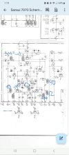
So I've done quite a bit of probing today with F2624 inserted. I will attach a photo of the schematic with my voltages scribbled on them :)

All negative voltages are fine. My positive ones are shy of what the schematic calls for. These are the voltages being sent off TR01 on the main power board. My relay still isn't clicking with F2624 in place. Could just these couple of volts missing be my problem?
All my the other voltages are correct on the F2624 indicating that the compenants are doing their job and I did not mess anything up when I installed them... I believe.

I read on another forum to check the voltages on the NPN output transistors collectors for +44 volts. I have that. I have also check the outputs with my DMM and my Atlas DCA55.l and they appear to be good. They also said to check pins 10, 11, 22, 23 on the driver board while inserted for 0 volts. I have that as well.

So it appears maybe I am still having problems due to TR01 not being able to supply those +44 volts. I guess I'll order a couple replacements and see if they will make a difference.
 

Attachments

  • Screenshot_20231109_131940_Drive.jpg
    Screenshot_20231109_131940_Drive.jpg
    63 KB · Views: 21
Back
Top Bottom