• The move to the new server is done. There are some software and database maintenance updates in process. This has us passing the hat around to help out. We appreciate any donations. Seriously, even a dollar helps. The payment page may be found here - https://www.audiokarma.org/support.html

Sansui 7070 popping, dumping audio temporarily

He's right, they don't *need* to be matched. However closely matching them helps to steady the fluctuating DC offset that is common for these boards. Plus if you use KSC1845FTA all from the same batch, they're usually pretty close anyways and work well.
I have one of these I use quite a bit. https://www.amazon.com/gp/product/B00O0BMNX2/ref=ppx_yo_dt_b_asin_title_o06_s00?ie=UTF8&psc=1
And I have one of these for quick testing and identifying EBC, etc. Not super accurate, but close enough! And cheap too. :D https://www.amazon.com/Mega328-Digi...words=transistor+tester&qid=1569871168&sr=8-9
I made my own test leads using short pieces 22ga silicone coated wire, and minigrabber clips.

I will order the cheap one, I acquired a couple other receivers, including a Sansui 1000x, so might as well get what I need. Thanks for all your help!

Another question. The main board has the two main power supply capacitors and a few smaller electrolytic capacitors. Should I change those as well? And what is the preferred cap for the big ones? I've been using Nichicon FG for the audio path, but power supply caps aren't in the actual audio path...
 
Possible, but I have a pair of original 501 (not series anything) I've re-foamed and they haven't caused any damage. Well, not yet anyways. :biggrin:
Understood, as I owned a pair of 501 and never saw any damage done either. But I never really pushed them above 50 watts. It would be good to check the resistance before hooking them up to the 7070 again. Anything significantly below 4 ohms should be cause for concern.
 
Last edited:
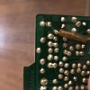
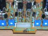
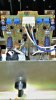
Here are pics of the board and the trimmers. I don't know if you mean the lead spacing or value. One of the trimmers says 7k. measuring the outer legs in the circuit, the outer trimmers are reading about 360 ohms, the inner trims are reading 3.5k, approximately.

Multi-turn pots are very nice, but not really necessary if you are careful and patient with single turn. You need to let us know which trimmers are on the board now. The 2 versions of the board used different trimmers.
347094F8-0A58-4508-97B3-3CF85AB55962.jpeg3FFF95B0-35A6-430F-A5C6-71B0ED948490.jpeg106BCBF0-5EC9-44B4-B07B-A0EBF7ADD11C.jpeg
 
Multi-turn pots are very nice, but not really necessary if you are careful and patient with single turn. You need to let us know which trimmers are on the board now. The 2 versions of the board used different trimmers.
You'll need the patience of a saint if you keep the original single turn trimmers :) - I find them impossible to use. And that trimmer which you think says '7K' will most likely be 4.7KΩ, and as with most resistors 'in circuit' you won't get an accurate reading unless they are removed. ;)

New single turn trimmers are OK, but I really feel multi-turn are so much better, but note that using them means that it is not possible to see 'where' they are adjusted to. Sometimes knowing where the 'slot' or 'pointer' (of a single turn trimmer) is, just by glancing at it, is useful to know. :)
 
Last edited:
You'll need the patience of a saint if you keep the original single turn trimmers :) - I find them impossible to use. And that trimmer which you think says '7K' will most likely be 4.7KΩ, and as with most resistors 'in circuit' you won't get an accurate reading unless they are removed. ;)

New single turn trimmers are OK, but I really feel multi-turn are so much better, but note that using them means that it is not possible to see 'where' they are adjusted to. Sometimes knowing where the 'slot' or 'pointer' (of a single turn trimmer) is, just by glancing at it, is useful to know. :)
A Saint? :rflmao: They're tricky, but not "Saintly" tricky. But yes there would be two 4.7K that get replaced with modern 5K, and the other pair are 1K and will be replaced with the same but modern 1K. Bourns is my choice of brand.
 
I will order the cheap one, I acquired a couple other receivers, including a Sansui 1000x, so might as well get what I need. Thanks for all your help!

Another question. The main board has the two main power supply capacitors and a few smaller electrolytic capacitors. Should I change those as well? And what is the preferred cap for the big ones? I've been using Nichicon FG for the audio path, but power supply caps aren't in the actual audio path...
Nichicon UKL for low leakage/noise and tantalum replacements
UPW for supplies
UKA for signal path
 
The problem is the sideways adjustment. The top slot would be better. However the single turn will be perfect and you can adjust them with the bracket in place through the original access holes.
5K single turn.. https://www.mouser.com/ProductDetail/Bourns/3386X-1-502TLF?qs=sGAEpiMZZMu7u4aXTvZ%2Bj89PqHIs2OKck%2BGUPXHz5Ns=
1K single turn... https://www.mouser.com/ProductDetail/Bourns/3386H-1-102LF?qs=sGAEpiMZZMu7u4aXTvZ%2Bj7mpVAXHoGAhBYoCHzUEu6Y=
And the Datasheet.. https://www.mouser.com/datasheet/2/54/386-776606.pdf
But the multiturn do work nice, but you have to adjust them in before installing the hold down bracket.
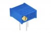
Oh, ignore the picture. Mouser just uses a "generic" Bourns photo. The datasheet shows the right ones with dimensions, orientation, and pins.
 
Here's the difference between the top slot multiturn, and the single turn..
 

Attachments

  • Single turn trimmers.jpg
    Single turn trimmers.jpg
    184.6 KB · Views: 20
  • Top Slot Bourns F-2624.jpg
    Top Slot Bourns F-2624.jpg
    48.8 KB · Views: 19
One more thing. I’m trying to get the values for all the electrolytic capacitors on the motherboard. Of course I got the bigger ones but the little ones are more difficult and the values are obscured due to the position, in some cases. The service manual doesn’t show the values for all the caps.
 
What is the board number? Are you attempting to read values with the board in place? You may need to remove (or partially remove) the board in question in order to get a better view of the values.
 
One more thing. I’m trying to get the values for all the electrolytic capacitors on the motherboard. Of course I got the bigger ones but the little ones are more difficult and the values are obscured due to the position, in some cases. The service manual doesn’t show the values for all the caps.
Sure it does, just not in the board layout parts list. Look in the schematic. ;) Note that in the case of Left CH vs Right CH (driver board, EQ board, Tone board, etc), only one side will have the value written. In that case just multiply x2 for each. Power supplies, mainboard, ancillary boards, etc should have each value indicated since they're usually not Left, or Right dependent.
 
All 4 of the 2SC1400 should be gain matched as close as possible. They will effect DC offset. There are many threads here for the F-2624 driver board, which was also used in the 8080DB, 9090DB, and QRX-9001. Plus there are two variants. Early models used a transistor for BIAS tracking, and the later models used the STV-3H diodes for BIAS tracking and some of the components are a little different between the two versions. However, the complete boards themselves can be interchanged upwards meaning the 9090DB board can be used in the 7070, but the 7070 board can't be used in the 9090db unless you change a few transistors because of voltages.Otherwise they are the same basic designs.
It sounds like you will need to check both the DC offset voltage, and the BIAS current as it sounds like they are probably too high right now. The "protection" circuit is where you'll find the speaker relay. It sounds as though that circuit is working and doing it's job.

Ok, so I ordered the transistors, went with ZTX694B transistors. I needed 4, ordered 8. These are the gains:
1.01k, 713, 970, 761, 868, 1.04, 814, 753.

Should the pairs be gain matched per channel? Like say, TR01 and TR03 matched, then TR02 and TR04 matched? Or should the gains be matched across the left and right channels? Like match TR01 and TR02, then TR03 and TR04?

My instincts are telling me to put the two 1k transistors in TR01 and TR02 and then 761 and 753 for TR03 and TR04...
 
Ok, so I ordered the transistors, went with ZTX694B transistors. I needed 4, ordered 8. These are the gains:
1.01k, 713, 970, 761, 868, 1.04, 814, 753.

Should the pairs be gain matched per channel? Like say, TR01 and TR03 matched, then TR02 and TR04 matched? Or should the gains be matched across the left and right channels? Like match TR01 and TR02, then TR03 and TR04?

My instincts are telling me to put the two 1k transistors in TR01 and TR02 and then 761 and 753 for TR03 and TR04...
You match Pairs for each channel. TR01,03... 02, 04. They have a common emitter. Look in the schematic and you'll see what I mean. ;)
 
You match Pairs for each channel. TR01,03... 02, 04. They have a common emitter. Look in the schematic and you'll see what I mean. ;)
Ok, understood. But what about the gains from the channels? Does it not matter if one channel has transistors with higher gains? Since I only got 8 transistors, I have limited options here.
 
Back
Top Bottom