• The move to the new server is done. There are some software and database maintenance updates in process. This has us passing the hat around to help out. We appreciate any donations. Seriously, even a dollar helps. The payment page may be found here - https://www.audiokarma.org/support.html

Sansui 800 trouble shooting - blows speaker fuse after deoxit

Jmauer

New Member
I bought this stereo at a thrift store for $15 about 6 months ago and have been using with some old speakers that I also thrifted. We really like the sound of it and my girlfriend and I have been trying to learn a bit about it. I guess we are noobs to the audiophile world.

I thought the volume pot needed replaced but she read somewhere that it probably just needed cleaned and worked, so she ordered a tube of deoxit as recommended.

I applied it to the bass, treble, volume, and balance pots last night by removing the housing and dripping it directly into them through the little square holes, as directed. It looks like I used a little over half of the 2ml tube in total.

Meanwhile, I rewired my speakers in series to increase their impedance values, because I read that the the proper impedance for this unit is 8 ohms.

It was like this: (and it was REALLY loud, had it to keep it at about 25% volume max.)
Channel A) 2x 3.2 ohm speaker cabinets wired separately to R and L
Channel B) 2x 2.6 ohm speaker cabinets wired separately to R and L

After rewiring, Channel B is now unused and Channel A is now wired as follows:

Positive output RIGHT --> positive terminal 1st speaker cabinet (+2.6 ohms)
neg. terminal 1st speaker cabinet ---> pos. terminal passive subwoofer cab (+3 ohms)
neg. terminal subwoofer ---> positive terminal 2nd speaker cab (+2.6 ohms)
neg. terminal 2nd speaker cab ---> Negative output RIGHT

Positive output LEFT ---> positive terminal 3rd speaker cab (+3.2 ohms)
neg. terminal 3rd speaker cab. ----> pos. terminal 4th speaker cab (+3.2 ohms)
neg. terminal 4th speaker cab ---> Negative output LEFT

so on channel A that's 8.2 ohms to right and 6.4 ohms to left, right?
channel b 0 ohms.


Back to deoxit:

I'm worried I used too much of it and didn't wait long enough because I powered the unit back on to test the new wiring layout, about 2 hours or so after applying it.

It instantly blew the Left speaker fuse and I instantly went to bed.

This morning I started troubleshooting by taking the speaker wire from the Left (blown) output and putting it in the right. Powered the unit up and the right side played fine through those speakers, so I don't think there is a problem there with the wiring of either set of speakers(!)

Then I plugged the other set of speakers into the Left output and switched the non-blown fuse over. It blew as soon as I powered on. (there was also a popping noise through the speakers that didn't happen on the right side.)

So I went to I went on a scavenger hunt to get more 250v 2.5 A fuses. I plugged in two new fuses and powered on the unit without any speakers hooked up at all. It instantly blew the same L fuse again.

I only have two working fuses left! (they were hard to find!)

My theory is: the speaker wiring is fine but there is either still unevaporated detoxit in the pots
OR there WAS unevaporated detoxit in the pots last night and the short caused damage somewhere else in the unit.

I'd really like to figure out how to diagnose and fix it properly but I'm an amateur so I'm open to workarounds if they exist...

Thank you for reading!
 
Last edited:
Register to hide this ad
Welcome to A.K. @Jmauer
I don't think your speaker combinations are 8 ohms and may have blown something. I'd try to find a pair of speakers at rated.
recommend built a Dim Bulb Tester. read up on it.. if the bulb stays bright you have a short somewhere.
upload_2022-2-25_14-41-24.png
 
Last edited:
Welcome to AK.

Messing with speakers wires is the 1st cause of blown amps. I suspect5 something went wrong the 1st time and now you have a blown output.

Fitting new fuses is not a good idea. The unit won't fix by itself. It needs to be repaired.

I don't think the deoxit is related to the fail. The only suspect things to me are: speaker wiring and amplifier assembly (something shorted inside the amp, some wire, a screw pressing a wire, a wire strand left inside the unit, things like that)
 
O.k., Tomorrow morning I will build a dim bulb tester.

also worth noting that the unit has the schematics inside an envelope taped to the bottom of it. And luckily my girlfriend still knows how to read schematics from when she was in college. We also have a digital multimeter and soldering iron ready to go. So I'm really hoping for troubleshooting tips after I do the dim bulb test!

Thanks so much.
 
I built the dim bulb tester. The bulb flashes briefly when the 800 is powered on, then goes completely out. (40w bulb. the 800 is supposed to draw 18VA without signal)

Am I correct in thinking that this indicates that the problem is somewhere in the left output past the blown fuse, and that there is not a short anywhere else in the unit?

heres a picture (*edit: of the dim bulb tester)

https://drive.google.com/file/d/1xKzFibqx3_2O6v7K88sCZ1rSSFubMAeP/view?usp=sharing
view
 
Last edited:
Sounds like an output transistor likely blown. Q? is how much experience do you have? i.e. testing transistors, DMM and knowledge or soldering?
schematic. https://www.hifiengine.com/manual_library/sansui/800.shtml

OP's link is his DBT and page is slow loading.

My girlfriend (Grace) is a physics professor and I am a Neanderthal (welder). So, we have zero experience with home audio but she is good with schematics, multimeter, and soldering we can handle.

Grace is looking at our print copy of the schematics now with your suggestion in mind...
 
she is good with schematics, multimeter, and soldering we can handle.
She sounds like a keeper! :thumbsup: apply lots of 'encouragement' (bribery works)
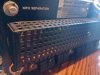
Look at the heat sink where you'd see transistors.. those are the outputs.
link to check transistors. you really need to look around under the cover.. Pics welcome close up to see whats inside.. sometimes we see stuff.
https://audiokarma.org/forums/index.php?threads/bipolar-junction-transistor-testing-basics.43186/

post back on transistor part numbers if you find a dead one(s).
 
Ok, so she did a bunch of testing but without removing any components:
-All transistors (8 between L and R) on F-1100 boards tested good
-Both transistors on the F-1094 board tested good
-two of the four 2SD180 transistors on the back of the unit tested bad. I don't see a heatsink but these four transistors hang out of the back of the box and have a guard over them.

Seems like we need to pull these two and retest them independent of the system to verify?

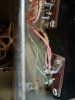
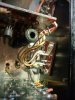
IMG_20220225_133850.jpg IMG_20220225_133904.jpg
 
I built the dim bulb tester. The bulb flashes briefly when the 800 is powered on, then goes completely out. (40w bulb. the 800 is supposed to draw 18VA without signal)

Am I correct in thinking that this indicates that the problem is somewhere in the left output past the blown fuse, and that there is not a short anywhere else in the unit?

heres a picture (*edit: of the dim bulb tester)

https://drive.google.com/file/d/1xKzFibqx3_2O6v7K88sCZ1rSSFubMAeP/view?usp=sharing
view
If you didn't replace the blown fuse before testing with the dim bulb tester you won't see a problem.

If 2 outputs are blown there may be other damage further back. Mark the schematic where the blown outputs are and trace back, any resistors and the drivers would be next.
 
If you didn't replace the blown fuse before testing with the dim bulb tester you won't see a problem.

If 2 outputs are blown there may be other damage further back. Mark the schematic where the blown outputs are and trace back, any resistors and the drivers would be next.

If I put a fuse in and power it on, it blows the fuse.

and sorry, what are "drivers"? by blown outputs, do you mean the transistors that tested bad?
 
If I put a fuse in and power it on, it blows the fuse.

and sorry, what are "drivers"? by blown outputs, do you mean the transistors that tested bad?
The whole purpose of the dim bulb tester is to limit current in the event of a short. It does that by glowing brightly, and thus limits the current as the filiment's resistance rises with heat. No matter, you're hot on the trail.

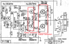
The transistors you found shorted on the back panel are the output transistors:
upload_2022-2-25_14-5-0.png
Continue to check back toward the front end of the output stage. You found bad outputs, now check the drivers and the associated resistors for damage.
 
Grace here (OP's partner in crime),

After disconnecting all the output transistors, it looks like only one is shorted. What part should I order for it (original is NEC 2SD180), and is there any reason to replace both in the pair, even though only one is bad? With all the outputs disconnected, it passes the dim bulb test (with fuses in). Does that mean there's not another short downstream, and once I replace the outputs we should be good to go?
 
*bump

Grace in the house.
Grace here (OP's partner in crime),

After disconnecting all the output transistors, it looks like only one is shorted. What part should I order for it (original is NEC 2SD180), and is there any reason to replace both in the pair, even though only one is bad? With all the outputs disconnected, it passes the dim bulb test (with fuses in). Does that mean there's not another short downstream, and once I replace the outputs we should be good to go?
 
Welcome to AK.

Like Sherwood on their early 70s models, use the back panel as a heat sink and put a cover over the output transistors. One sheet I have where they give the bias current also states 18W continuous into an 8 ohm load.

Common choice I usually go with the the Onsemi MJ21194 (NPN), if it is out of stock the MJ21196 should be very similar. There is a G on the end of the current model being sold. Mouser and Digikey are common suppliers I usually order from.

I usually replace as a pair. They work together. Have acquired several fix and repair vintage units where they replaced just one and blew the channel up again. Also check the trimmers sometimes other components can get fried when an output goes. Also read about adjusting the channel voltage and bias current for the channel. Changing components should require adjustment. Those being way off can blow your new components. Those old trimmers can oxidize and go open and blow things up.

The driver transistors are the transistors in the red box on the left in the diagram Ray provides above, they drive the output transistors. Sometimes when an output blows, a driver transistor can also get damaged. Diagram shows 2SC734 and 2SA561 my unit has the transistors shown on the schematic. Sometimes they substitute in manufacturing and transistors in unit may not match schematic. Should be the pair of transistors behind and to the left of the big trimmer on the amp card.

On cap coupled units one transistor is adjusted to around half the voltage of the power supply voltage from the filter cap. The filter cap is the biggest capacitor in the chassis, it is over by itself on the left side of the chassis. Big 2000 uF 80V grey Elna. Measure at the terminal with the brown wires. Usually good starting point. Then there is a bias current across the output transistors. Helps reduce crossover distortion but too much can cause a channel to run hot and at an extreme blow. Information I have shows 22.5 mA, Sansui historically loved specifying taking out the channel fuse and measuring the current across the fuse holder.

Figure someone kept putting new fuses in or classic approach put a bigger one instead and that is why the 800 fix and repair I picked up before Christmas instantly blew the chassis fuse as soon as the power switch was pushed. Found a shorted rectifier diode, wonder if it pulled too much current too many times. Figure it needs a good restore before doing much with it, guy said an amp channel fuse was blown when he got it. He had replaced it and the chassis fuse and the chassis fuse blew instantly when power was applied.
 
Grace here (OP's partner in crime),

After disconnecting all the output transistors, it looks like only one is shorted. What part should I order for it (original is NEC 2SD180), and is there any reason to replace both in the pair, even though only one is bad? With all the outputs disconnected, it passes the dim bulb test (with fuses in). Does that mean there's not another short downstream, and once I replace the outputs we should be good to go?
Sorry I didn't see this, Grace. You need to check the resistors and the driver transistors as well. Often when outputs go there's collateral damage, as @dly66 mentions above. Do you guys have a digital multimeter?
 
driver transistors and resistors look good, so do the rest on that board. I'll order the new outputs and read up on adjusting the bias current. Thanks!
 
Back
Top Bottom