• The move to the new server is done. There are some software and database maintenance updates in process. This has us passing the hat around to help out. We appreciate any donations. Seriously, even a dollar helps. The payment page may be found here - https://www.audiokarma.org/support.html

Sansui 8080DB dolby board

amr2

Well-Known Member
Hello

I need some help with this receiver. Someone has worked on it, and the signal is lost in this board. I have signal until tape 1 rec output. The dolby switch have been disassembled, and the wafers are all different, perhaps someone have any information about their positions. On the other hand its a pain on the ass follow the signal path, I can not find the the physical pinout of the switches on the service manual, and neither does the numbering of the ribbon cable.
 
Last edited:
Register to hide this ad
I had a very similar issue to you, one I have yet to be able to resolve. The Dolby board's rod that connects all the wafers likes to walk out. I could not get my board working and ended up bypassing it.

Here is my troubleshooting thread. User AE Bob was kind enough to go over continuity for each pin on his working 9090db Dolby board. There is also info on how to bypass the signal if you chose (disables the two Tape inputs), as well as further tracing of the signal. It's a mess, I spent two full days of armpit sweating attention, not something I would like to do again. Good luck, please provide photos if you can if you get it working.

https://audiokarma.org/forums/index.php?threads/9090db-dolby-board-help.917332/

One note, the metal that holds the wafers in place is not going to take kindly to repeated bending. Leave the leaves bent outwards as you troubleshoot, only bending them back in once you confirm functionality.

upload_2021-1-11_15-29-29.png
 
Hello

I need some help with this receiver. Someone has worked on it, and the signal is lost in this board. I have signal until tape 1 rec output. The dolby switch have been disassembled, and the wafers are all different, perhaps someone have any information about their positions. On the other hand its a pain on the ass follow the signal path, I can not find the the physical pinout of the switches on the service manual, and neither does the numbering of the ribbon cable.
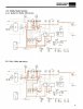
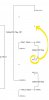
Oh boy, I hate going into a unit that someone already messed things up. I always mark each wafer before disassembly. I use a felt tip marker and put one, two, etc marks for each one, and on one side only. I use the left side. That way I know which is first, and which way they face. Plus I never rotate the hub more than 1/8 turn when cleaning because you can get 180 degrees out of rotation. I don't have any switches out to take photos of, sorry. Perhaps someone else does. It's a pain, but you can use this section of the SM (assuming it is correct) to trace out the switch wafers and match them up.
Dolby switch layout.jpg
 
Thank you very much for all the information! Things will be easier now :)
I'm pretty sure that the wafers are in the wrong position, it will be the first thing to check.
I will report back.
 
The problem was that some wafers where 180 degrees rotated. Thanks to CDFixer guide I was able to put each wafer in their position. I'm going to service all the board, including the bridges between sides and test it.
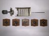
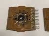
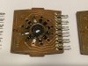
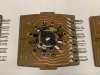
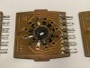
Some pictures in OFF position, from 1 to 5

IMG_6531.jpg IMG_6532.jpg IMG_6533.jpg IMG_6534.jpg IMG_6535.jpg IMG_6536.jpg
 
The problem was that some wafers where 180 degrees rotated. Thanks to CDFixer guide I was able to put each wafer in their position. I'm going to service all the board, including the bridges between sides and test it.
Some pictures in OFF position, from 1 to 5

View attachment 2098078 View attachment 2098079 View attachment 2098080 View attachment 2098081 View attachment 2098082 View attachment 2098083

Nice job, thanks for the nice photos. I compared your photos to mine and they are different. Can you confirm that these orientations are the way you installed them with success?
 
They are only tested with the multimeter following each position showed in the guide (1 to 5). The plan now is clean the wafers, rebuild the board, install the selector as showed in the pictures and test it. I will report the result..
 
By the way, some tech has changed all the capacitors with crappy ones :no:
Does anyone have a recap list to check the types and values? I will recap it again
 
Last edited:
https://audiokarma.org/forums/index.php?threads/9090db-recap.917709/

I used 63v to replaced 16v caps for no reason other than convince with the whole order. Feel free to choose whichever voltage rating you would like.

F2655 Dolby NR Circuit Board

Electrolytic Caps
C-605 100uF 6.3V E.C 4mm 647-UPW1E101MED1TD 25v
C-09 10uF 16V E.C 5mm 647-UKL1J100KED 63v
C-10 10uF 16V E.C 5mm 647-UKL1J100KED 63v
C-11 10uF 16V E.C 4mm 647-UKL1J100KED 63v
C-12 10uF 16V E.C 4mm 647-UKL1J100KED 63v
C-13 10uF 16V E.C 4mm 647-UKL1J100KED 63v
C-14 10uF 16V E.C 4mm 647-UKL1J100KED 63v
C-15 10uF 16V E.C 4mm 647-UKL1J100KED 63v
C-16 10uF 16V E.C 7mm 647-UKL1J100KED 63v
C-19 10uF 16V E.C 4mm 647-UKL1J100KED 63v
C-20 10uF 16V E.C 4mm 647-UKL1J100KED 63v
C-21 10uF 16V E.C 4mm 647-UKL1J100KED 63v
C-22 10uF 16V E.C 3mm 647-UKL1J100KED 63v
C-29 10uF 16V E.C 4mm 647-UKL1J100KED 63v
C-30 10uF 16V E.C 4mm 647-UKL1J100KED 63v
C-35 10uF 16V E.C 647-UKL1J100KED 63v
C-38 10uF 16V E.C 4mm 647-UKL1J100KED 63v
C-606 100uF 16V E.C 5mm 647-UPW1E101MED1TD 25v
C-01 47uF 16V E.C 3mm / 6mm 647-UPW1V4R7MDD 35v
C-02 47uF 16V E.C 3mm / 6mm 647-UPW1V4R7MDD 35v
C-41 1uF / Audio 50V E.C 2.5mm / 5mm 505-MKS21.0/63/5 63v
C-42 1uF / Audio 50V E.C 2.5mm / 5mm 505-MKS21.0/63/5 63v
C-608 1uF / Audio 50V E.C 2.5mm / 4mm 505-MKS21.0/63/5 63v
C-36 10uF / Audio 25V E.C 5mm / Audio 647-UKL1J100KED 63v
C-37 10uF / Audio 25V E.C 5mm / Audio 647-UKL1J100KED 63v
 
Last edited:
Thank you! :beerchug:
Do you know if the rest of the boards are the same as the model 8080? There are bad chinese capacitors everywhere :mad:
 
No. The DB models are different than the non-DB models.
Sorry I meant 9090DB and 8080DB. As far as I can see both models share many boards. I will use MIJ_Pioneer recap list and the service manual to check the installed capacitors
 
Last edited:
Last edited:
By simple coincidence I'm looking at buying a spare Dolby board and note that in the service manual I have there are two stock numbers for this board, one for the 9090DB and one for the 8080DB. The same service manual of course only has the one schematic covering both boards..
 
Back
Top Bottom