• The move to the new server is done. There are some software and database maintenance updates in process. This has us passing the hat around to help out. We appreciate any donations. Seriously, even a dollar helps. The payment page may be found here - https://www.audiokarma.org/support.html

Sansui 8900ZDB Thermistor

tinkerer

AK Subscriber
Subscriber
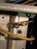
Anyone have any information on a PR1 Thermistor that is part of the Protection Circuit on a Sansui 8900ZDB. The board is a 3301. The PR1 attaches to the main heatsink so I assume it is a heat coupler of some type.

I have been in a wrestling match for several months now with this 8900ZDB and have had the amp and protection boards loose off and on several times. All the wiggling finally broke one of the wires right at the teardrop. I don't see how it is repairable. Totally a bone head on my part.

Is there any type of replacement?
Can this be bypassed?

Thanks for any help and IMG_1866.JPG suggestions.
 
Register to hide this ad
Are you sure that is the right part number Lee? it refers to a mechanical TO-220 thermostat, whereas the picture shows what looks like a bead thermistor?
 
Last edited:
As I remember without schematics in front of me that is a temp sensor that shuts down the outputs if the heatsinks overheat rather than a thermistor.
 
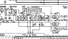
Here it is - right in the middle just below the HA12002 - connected to pin 4

upload_2016-10-2_16-21-53.png

Does that help to jog your memory?
 
Even if the lead is broken off you should still be able to touch the stub with an ohmmeter probe. Measure the value while heating and cooling it. That should give you a reference value to help find a substitute. If nothing else, it would give you a reference value to bypass it with a fixed resistor.

- Pete
 
The HA12002 is used as a speaker dc and amplifier heat sink monitor chip. Pin 4 responds to a thermal runaway condition and triggers an internal relay once a certain temperature is reached. A thermistor will provide enough resistance rise to induce cutoff if you can figure out what that value is, I feel that a thermal switch is more reliable thus the part recommendation, plus you know for sure the circuit will shut down as the heatsinks overheat. Just my old .02 as usual :)
 
Well the picture provided looks like the thermistors used in the BA-5000, BA-3000 and AU-9900 and AU-11000, which are actually Posistors type PTH487A = NLA. I checked the DC resistance of one when I had the chance and it was 320Ω @ 20ºC, however I am not at all sure that these are the same as the one pictured. I imagined the HA chip would want to see a resistance rather than an open circuit as provided by a thermal switch. And if it IS a Posistor - the HA will want to see a high resistance with high temperature - obviously the other way round if it is an NTC thermistor.

See post #240 in this thread, and also the last pic of post #248.
http://audiokarma.org/forums/index....-help-for-my-first-restoration.552152/page-12
 
Last edited:
Overundr1, Hyperion, LBPete, you guys are great. Really appreciate it.

I cannot get a ohm reading between the knub and the attached wire, nor the knub to ground.. I can get a reading of 835 ohms between the attached wire and ground. Attached or unattached to the heatsink makes no difference.

I kinda like the idea of the Sensata mechanical switch that Overunder1 has used. I can mount it right to the heatsink like the original. The trick is, as I see it, is to select the proper temp. The Sensata 723-1194-ND switches at 149 degrees F and resets at 104 degrees F. If that heatsink is 149 degrees the outputs have to be quite a bit hotter I would think. Opinions?

The Sensata switch is also Normally Open and would close at the 149 degrees. So.....looking at the circuit I am not good enough to tell if that switch should be NO or NC. Am I looking for a NO or NC switch?

Thanks.....Jim
 
I believe that yellow thermistor is NO, so I'm going to extract it off the board and apply some heat to see if it closes and gives an ohm reading.
 
As far as I know that thermistor isn't an 'on-off device', it is basically a resistor, which is why I am puzzled by the suggestion to use a thermostatic (on-off) switch as a replacement. The IC is expecting a changing voltage at pin 4 for operation, this is provided with a resistive device in the PR1 position.

I can only guess that Lee has remembered the part number incorrectly, repaired one in the past, and forgot the equivalent he used - very easy to do unless you make copious, time consuming notes.

I would advocate repairing the original device, to restore functionality as described by LBPete, or fitting a 330 ohm or 390 ohm resistor in its place again LBPete, remembering that thermal protection is rendered inoperative in this case. Lastly, find a replacement from somewhere, or an equivalent - if we can assume that it is a 'PTH487A' device, which is a thermistor with a positive temperature coefficient. (i.e. resistance increasing with temperature)
 
Last edited:
The SM does list it as a Thermistor, which would indicate, as you say, an increase in resistance as temperature rises. I have heated the PR1 and still cannot get any ohm reading. Possibly the PR1 is defective which may be why the amp cooked several things when it went belly up. As far as I'm concerned the protection system didn't work in the first place, so if I l can put in a sub in the form of a resistor, or another heat sensing device, then I don't have a problem loosing the thermal protection.
 
OK I removed some of the epoxy around the nub of the broken wire, evidently I wasn't getting a connection to my DVM. I now get around 165 ohms at room temp. Upon heating the Thermistor the ohms steadily rise as heat increases. I stopped testing at 50K ohms. I don't have a way of knowing what the temp of the Thermistor was as I heated it. I'm going to put in a 200 ohm resistor and test.
 
how about a thermal switch with a resistor in series and another in parallel so you can have a resistance transition at the operating temperature? Course you'll need to figure out how much resistance is appropriate...
 
Installed a 220 ohm resistor and the speaker relays work as they should.

But I still have something amiss. DBT indicates a short somewhere. I cannot set the bias on the right channel. I'll have to go back and check my work as I have rebuilt the amp board. Left channel is good.

This Receiver is being a royal PITA. Difficult to work on also. Not easy to get both sides of the amp board to solder/desolder.
 
Yes they are, been down that road before. The 220 ohm resistor idea was a good one setting a base line for the ic to work with, now think about the thermal switch. We do not have accurate data, or at least I never could find any as to what impedance level shuts that pin 4 off. Using a thermal switch at (pick your preferred temp point essentially does the same thing, breaking the circuit once a certain temp is reached, remember an open circuit will measure as infinite resistance.shutting off the speaker relay.
As far as the right channel bias recheck the orientation of the new outputs, the values on the emitter resistors and the (typically) metal oxide resistors that feed them. Again, being at work I have no access to the schematic so working from memory, perhaps John will post the circuit for us to work from.
 
Quote ---
"As far as I know that thermistor isn't an 'on-off device', it is basically a resistor, which is why I am puzzled by the suggestion to use a thermostatic (on-off) switch as a replacement. The IC is expecting a changing voltage at pin 4 for operation, this is provided with a resistive device in the PR1 position."

Yup, we on the same page, my solution is just a bit more abrupt :)
I guess given the scarcity of info on the original part coupled with a desire to prevent a thermal meltdown led me to use the switch and yes the last Z i worked on also had a broken thermistor amongst other mayhem. Thanks as always for the input John, very much valued;
-Lee
 
Ok, protection circuit cropped snapshot already posted in post #5. Just now I am not sure if the HA IC wants to see a voltage increase or a decrease for it to trigger. You could experiment with a toggle switch and a couple of resistors until you are satisfied with the triggering action, I would be wary of shorting pin4 of the IC to ground, my gut feeling is that it should see some resistance, obviously it can handle the resistance of the thermistor at room temp. The HA12002 is no longer made, but is available - at a price, so you need to avoid damaging it with this modification, or the testing for functionality.
 
Last edited:
Back
Top Bottom