• The move to the new server is done. There are some software and database maintenance updates in process. This has us passing the hat around to help out. We appreciate any donations. Seriously, even a dollar helps. The payment page may be found here - https://www.audiokarma.org/support.html

Sansui 8900ZDB Thermistor

I"m going to tackle the Thermal Protection first. The bias I'll get to after I figure that out.

Lee: I'm still trying to determine if a thermal switch will work in this application. Not that I'm opposed to it. The part John has pointed out would seem to work much like the original.

John: The one thing I don't understand about the PTFM04BE222Q2N34B0 is: as the temperature rises so does the resistance, and the resistance starts at 330 ohms and tops out at 2.2K ohms with a temp of 130 degrees C or 266 degrees F. ( Or at least that's the way I read the specs) Are you thinking the IC will see the voltage drop or increase somewhere along the way in order to disconnect the speakers, well before it gets to 266 F? I should probably try a 330 ohm resistor to see if the speaker relays still work even though I suspect it would.

One other issue is that I don't want to keep soldering and desoldering to those solder pads. Too much and I'll ruin one or both pads. They are very close together, small, and not easy to get to. So I'm not sure I want to do a lot of experimenting with different resistors etc. I'm going to leave the IC alone. I've taken measurements from an IC before and it's tricky, easy to slip off a pin and short to next pin, even with just the very tip of the probe exposed.

Thanks for all the discussion and suggestions guys, appreciate it.
 
Well, about the thermistor, there are 2 main kinds 'PTC' and 'NTC' - Positive Temp Coefficient and Negative Temp Coefficient, your one I feel sure is a PTC so the resistance rises with temperature, (you can check this with your multimeter if you can get a connection). NTC is the other way round. Note well - There is no requirement for the thermistor to be heated to the max, as it is a basically a resistor with very poor temp stability. so it just has to alter its resistance enough to trigger the IC. The amount the resistance changes with temp could be 1Kohm or 10Kohm it just depends on the thermistor.

To be honest I am not sure the one I posted a link to has enough resistance change to do the job, if you decide to try it, it may be a case of suck-it-and-see. :)

As I said, the use of the thermal switch depends on you doing some experiments to find out what voltage change the IC wants to see on pin4 to trigger, and in what direction up or down? - it won't be much - something like 2 or 3 volts will be enough I think.
 
NTC's are fairly linear, and that's by design. PTC's are not. As they warm up, resistance rises fairly slowly and evenly, but there comes a point where the resistance suddenly rises very quickly. This point is called the knee (for obvious reasons). The point here is that matching the original resistance is not required...probably anything between 100 ohms and 1K (and probably more) would be cool, as long as the device is capable of rising to 1000x that value when the temp gets to an appropriate level.

The Murata devices do a decent job, but Murata rates them funny. Murata rates the device pretty low on the knee, whereas most circuits are looking for a significantly higher value to trip a protection circuit. So, I'd look at the 'BH' device, which Murata rates at 60°C. It hits 1000x the 25°C value at about 78°C.

Mouser #81-PTFM04BH471Q2N34B.

Overunder1's idea of using a thermal switch is OK (I think), but you'd need a NC switch, not a NO one. Maybe something like this:
http://www.digikey.com/product-detail/en/cantherm/B12B06505AEDA0GE/317-1448-ND/1986492

That's a NO type. The NC type would be B12A06505AEDA0GE. That one might be tougher to find. I'd also want some series resistance in there, like 220 ohms or something.
 
Thanks Glenn, I couldn't make much sense of the Murata data sheet, so I sort of guessed the one I linked to would be ok, thanks as always for your advice and guidance. (I was nearly there :D)
 
Hi,

I had the opportunity earlier today to have a look at the specs of the HA12002, and the thermistor linked by John earlier today, but havent had the chance to post up my thoughts till now.

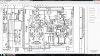
As I read this - Pin 4 of the HA12002 will be triggered if the voltage on the pin rises to 1.2v typical. Pin 4 is fed from the junction of the 150k R9 and the thermistor (and R9 and the thermistor forms a basic voltage divider). The supply voltage on the other side of R9 is approx 25v (pin 7 on the protector PCA). As the thermistor is in the order of several hundreds of ohms at 25 deg C the voltage at pin 4 will be in the order of 50mv at 25 deg C. For the voltage at pin 4 to reach 1.2V, the thermistor resistance has to rise or approx 7.5K ohms, or approx 16-20 times the resistance at 25 deg C. Glen, It looks like the on you linked would operate the protection circuit somewhere between 50 and 80 deg C assuming that a nominal value of 7.5K needs to be reached. In the one John previously linked, it would operate somewhere between 80 and 95 deg C. All assuming that I have interpreted the operation of the HA12002 and the thermistors correctly!!

Cheers

John
 
Last edited:
I have learned so much from you guys, along with having to educate myself about thermistors, couldn't have gotten this far without you. Thanks so much.
I will order Glenn's recommendation and give it a go. At worst I'm operational but without thermal protection. I have to put an order together, so it may be a few days, but I'll report back.
 
Now for the R Channel bias. I started checking everything and found Q14 to be improperly marked on the circuit board. I had replaced the 2SC1904 with a KSC3503 and installed it according to the ECB labeling on the board. According to the schematic the Emitter (E) should be connected to one leg of VR1 which is used to set the bias. If installed according to the labeling on the board that would put Base (B) connected to one leg of VR1. I installed a fresh KSC3503 reversing the pinout and I can dial the 2mV in with no problem. I set it at 1mV since I am still on the DBT.

However, I'm still not sure everything is in order. The DBT starts bright an immediately dims to almost no glow, and then brightens just slightly and holds. From my past experience the bulb should not glow at all. Is that correct or is it normal to have a low glow 8900ZDB Amp Section.jpg with this size receiver? I am using a 100 watt bulb8900ZDB Amp Section.jpg
 
Re: DBT action, that sounds about right to me. You can adjust the bias on both channels? - exactly the same 'feeling' from both channels? - No excessive DC offset? - and you can adjust the DC offset, if not actually zero it? - if the answer to these is yes - then (no speakers connected) give it a try.

BTW: your action turning the bias setting down to 'just a sniff' during DBT use, after checking you have proper bias adjustment, is spot on, this will allow you to 'see' a small reading straight away when it is off DBT. What you don't want to do is set the bias to the correct level ON DBT - and then power it direct from the mains - this would be VERY BAD - but you know that. :)
 
Yes bias adjustable in both channels and very stable. I rechecked after warm up and readjusted. Both R&L had risen to 25mV or so. After dialing it back down the bulb is almost totally out. I'm guessing new components burning in.
There is no adjustment for Offset that I can see in the Service Manual. But a DVM on speakers terminals show -1.0 to -1.8 L Channel, +0.5 to + 2.5 R Channel.

Went live - no smoke - warm up 15 minutes - set bias to 2.0 mV per spec - Making music :) Will recheck bias setting after a few hours of use.

Will report on the thermistor when installed.

Thanks again for everyone's help.

Jim
 
Well accomplished :)
A dbt will glow bright at first then dim down, you correctly noted and asked about it dimming all the way out. With the larger receivers that have a higher quiescent draw the bulb will stay dim but still glow a bit. Note, with the lower powered equipment drop the bulb used to 60 watts for medium powered and for the little ones you could drop down to a forty watt bulb. As an example, I just finished up two Pioneer sx-1980's and used 150watt bulbs for start up and they only go to dim not off. Tube equipment is a different deal all together, I use a variac and a isolation transformer both for safety and forming of caps.
 
I installed the PTFM04BH471Q2N34BO Thermistor and everything works as it should. Ran the unit for a couple days without issue. The heatsink works well on this unit and only gets slightly warm, so I doubt it will ever get hot enough to trigger the speaker relay, I think something would be toast before the Thermistor ever tripped the relay. At any rate I'm running good.

Thanks everyone, appreciate the help.

Jim
 
Back
Top Bottom