• The move to the new server is done. There are some software and database maintenance updates in process. This has us passing the hat around to help out. We appreciate any donations. Seriously, even a dollar helps. The payment page may be found here - https://www.audiokarma.org/support.html

Sansui 9090 re-cap gone bad

Dougi

New Member
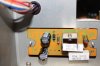
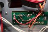
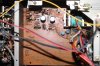
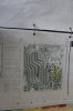
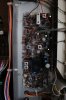
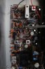
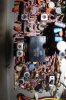
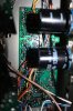
My Sansui 9090 (non DB) would not come out of protection mode, so I did some research on this site and from the help of past posts it wisely lead me to look at the F2436 driver circuit board. At location R30 I found a bad/open fusible resistor, so I replaced it along with 11 other resistors, 4 capacitors, and 4 transistors that were included in the kit I bought online from Vintage Stereos LLC (qrxrestore.com).

My Sansui was working again and sounding GREAT !!! I was so happy my first circuit board re-cap job was a great success. So I decided to order a complete stereo re-cap kit from the same outfit.

With the parts included in the kit I re-capped the following Circuit boards:
F2542 Accessory Switch
F2546 Power Supply
F2547 Protection
F2541 Equalizer
F2431 Power Supply
F2549 FM-AM Tuner
F2545 Filter and Muting
F2544 Tone Control
F2543 Tone Control
and upgraded Main Filter Caps to 80v 12,000uf.

I power up my beloved Sansui 9090 for the first time since the complete re-cap and I heard a hum for a split second then the fuses blew at f03 and f04 on F2546 power supply circuit board. I pulled The F2436 Driver Board and replaced the fuses and powered it up again and POW the fuses blew immediately.

Does anyone have any suggestions where I should start to look for trouble? Keep in mid this is my first recap job. I carefully pulled and replaced each cap one at a time, took pictures watched polarity on the boards, not sure where I could have gone wrong. All suggestions are more than welcome.

Please help bring my Sansui back from the grave
 
Register to hide this ad
Man that will be hard... But let's see the work done (Pics)and maybe I can assist you.
What amp rating fuses are you using?
Do you have a DBT?
Did you did all the recap at once?
 
Verify the 8 output transistors at the back of the unit, make sure none are shorting or shot, replace if needed. Replace the blown fuses, pull out the F2436 driver amp and fire it up on a DBT.
What's the bulb doing? Out of protection? Don't get off DBT yet.
 
Thank you for the replies,
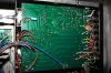
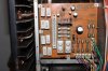
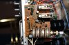
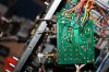
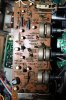
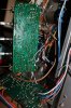
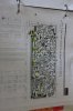
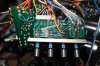
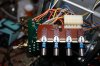
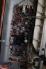
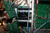
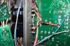
Hipocrates, here are some picks of f2431 power supply, more to follow

The fuses that blew on f03 and f04 on board f2546 are rated at 10 amps.

I don't have a dim bulb tester.

I was able to verify the unit still worked by plugging in head phones after I re-capped boards,
F2436 Driver
F2541 Equalizer
F2546 Power Supply
F2544 Tone control
Then after that I no longer verified.
 

Attachments

  • IMG_4931.JPG
    IMG_4931.JPG
    66.1 KB · Views: 58
  • IMG_4933.JPG
    IMG_4933.JPG
    40 KB · Views: 53
  • IMG_4936.JPG
    IMG_4936.JPG
    63 KB · Views: 56
F2541 Equalizer board
 

Attachments

  • IMG_4929.JPG
    IMG_4929.JPG
    102.1 KB · Views: 47
  • IMG_4934.JPG
    IMG_4934.JPG
    42.1 KB · Views: 40
  • IMG_4953.JPG
    IMG_4953.JPG
    103.3 KB · Views: 48
F2546 Power Supply board
 

Attachments

  • IMG_4926.JPG
    IMG_4926.JPG
    81.5 KB · Views: 53
  • IMG_4927.JPG
    IMG_4927.JPG
    71.1 KB · Views: 55
  • IMG_4935.JPG
    IMG_4935.JPG
    29.6 KB · Views: 49
F2543 Tone Control
 

Attachments

  • IMG_4949.JPG
    IMG_4949.JPG
    75.3 KB · Views: 33
  • IMG_4950.JPG
    IMG_4950.JPG
    94.7 KB · Views: 30
  • IMG_4954.JPG
    IMG_4954.JPG
    60.6 KB · Views: 27
F2544 Tone control
 

Attachments

  • IMG_4944.JPG
    IMG_4944.JPG
    66.9 KB · Views: 23
  • IMG_4946.JPG
    IMG_4946.JPG
    66.4 KB · Views: 21
  • IMG_4947.JPG
    IMG_4947.JPG
    46.4 KB · Views: 17
F2542 Accessary Switch Board
 

Attachments

  • IMG_4956.JPG
    IMG_4956.JPG
    83.1 KB · Views: 19
  • IMG_4957.JPG
    IMG_4957.JPG
    69.3 KB · Views: 18
  • IMG_4959.JPG
    IMG_4959.JPG
    52.2 KB · Views: 16
F2549 FM AM Tuner Board
 

Attachments

  • IMG_4966.JPG
    IMG_4966.JPG
    52.7 KB · Views: 21
  • IMG_4967.JPG
    IMG_4967.JPG
    52.7 KB · Views: 21
  • IMG_4968.JPG
    IMG_4968.JPG
    55.1 KB · Views: 20
  • IMG_4969.JPG
    IMG_4969.JPG
    56.9 KB · Views: 19
  • IMG_4970.JPG
    IMG_4970.JPG
    68.6 KB · Views: 21
  • IMG_4971.JPG
    IMG_4971.JPG
    58.3 KB · Views: 24
  • IMG_4972.JPG
    IMG_4972.JPG
    68.7 KB · Views: 20
the caps should be replaced by it's original polarity, not by PCB stenciling, check your photos
of the before against what you have now. skip the non-electrolytics, bi-polars, and focus
on only those that are polarized.

if only one is reversed - can destroy one or more caps and cause fuses to blow.
 
if you have a VOM/DMM, you can check resistance in the power supply section with the
power off and caps discharged. you might see a short in the bridge or a cap that's
shorted or damaged, and anything from rail to ground, etc.

polarity check - before pictures with after pictures. don't go by PCB markings.
since you have the boards out, trace the positives to ensure they are similar,
and then the negatives. one reversed makes for a bad day.
 
Did you pull the outputs and reinstall them? If so, check to see that they are in the correct locations.

Rob
 
the caps should be replaced by it's original polarity, not by PCB stenciling, check your photos
of the before against what you have now. skip the non-electrolytics, bi-polars, and focus
on only those that are polarized.

if only one is reversed - can destroy one or more caps and cause fuses to blow.

Thanks Bob, I did install the caps one by one however, I did rely on the printed circuit board for polarity, I will double check.
 
Verify the 8 output transistors at the back of the unit, make sure none are shorting or shot, replace if needed. Replace the blown fuses, pull out the F2436 driver amp and fire it up on a DBT.
What's the bulb doing? Out of protection? Don't get off DBT yet.

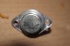
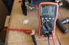
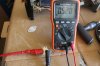
I pulled my output Transistors and all 8 test similar to the pictures enclosed about 0.5xx. Could you verify I tested this correctly by my picture, Multi meter is in diode mode , I believe they are ok.
 

Attachments

  • 200.JPG
    200.JPG
    26.5 KB · Views: 37
  • 201.JPG
    201.JPG
    75.2 KB · Views: 41
  • 202.JPG
    202.JPG
    79 KB · Views: 39
I pulled my output Transistors and all 8 test similar to the pictures enclosed about 0.5xx. Could you verify I tested this correctly by my picture, Multi meter is in diode mode , I believe they are ok.

They were carefully pulled one by one so they weren't mistakenly put in out of place.
 
Back
Top Bottom