• The move to the new server is done. There are some software and database maintenance updates in process. This has us passing the hat around to help out. We appreciate any donations. Seriously, even a dollar helps. The payment page may be found here - https://www.audiokarma.org/support.html

Sansui 9090DB Output Problems

CaseyWKC

Active Member
Been through this 9090DB, just finished pinning and recapping the dolby board that was previously preventing sound from passing through the pre in either channel. After the pinning all modes seem to work except for one channel in rec 2 that I plan on addressing later - but importantly - off - lets audio pass. I replaced all fusible resistors on the amp and protection boards. I have recapped the amp board and checked all drivers, diodes, the varistors, and zeners.

I replaced blown original outputs in this issue channel with new MJ21194/93G's.

I am getting very very low volume out of right channel. I can definitely hear it, but it's almost as if the relay is the issue or it's tiny, hooking up to a scope I see the volume level is next to nothing at the speaker outputs. I have also removed the relay and burnished contacts along with put a scope to the relay.

What's weird is I can trace it on my scope through the amp board through the cement emitters to the outputs and both sine waves from my generator look the same.

I've checked all the emitters as I thought this was an issue presenting itself when only a load was present.

I've also cleaned and deoxed these switches dozens of times. Everything else seems to work fine. Came to me with a myriad of issues at first, I'm in the final stages. Dolby board was the worst.

Thanks!
 
Register to hide this ad
Have you confirmed the output signal from the preamp? Can you drive the amp with a separate preamp?
Sorry I guess I wasn't the clearest in my post, but yes audio is perfectly balanced leaving the pres and even throughout the driver boards and to the outputs :headscratch:
 
So it seems you are saying the audio levels are good coming out of the amp board at the junction of the emitter resistors as one would expect.

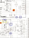
Follow the signal off of the the F-2656 to the F-2657. How about F-02, is it good? Wires to and from the speaker switch.

9090db.jpg
 
So it seems you are saying the audio levels are good coming out of the amp board at the junction of the emitter resistors as one would expect.

Follow the signal off of the the F-2656 to the F-2657. How about F-02, is it good? Wires to and from the speaker switch.

View attachment 3604417
Huh, I got nothing at F02, F01 is good. Checks good but no audio. In fact I threw in an 8A for testing instead of the 7A a couple of hours ago!
 
Last edited:
Huh, I got nothing at F02, F01 is good. Checks good but no audio. In fact I threw in an 8A for testing instead of the 7A a couple of hours ago!
Power the sucker off and start ohm checking the traces and wires between the last known good point and the fuse.
 
I'll bet you have a cracked joint on one of the output inductors L01/L02. ?

However that would likely mean you also have an open 4.7Ω resistor (R27/28 across the inductor) - so, maybe a cracked trace?

Incidentally, if you did this:-
I have also removed the relay and burnished contacts
You have very likely removed the plating on the relay contacts, the relay is now on borrowed time. ;)
 
Last edited:
I'll bet you have a cracked joint on one of the output inductors L01/L02. ?

However that would likely mean you also have an open 4.7Ω resistor (R27/28 across the inductor) - so, maybe a cracked trace?

Incidentally, if you did this:-

You have very likely removed the plating on the relay contacts, the relay is now on borrowed time. ;)
Oh I know, but I needed to make sure sound was getting through and it wasn't in the relay.

Replaced the fuse and the right channel is now fine, though the fuse tested fine before. Weird! Going to check those joints again but they looked fine last night.

Throwing in the outputs for the left channel and hopefully I'm ready to rock :).
 
Oh I know, but I needed to make sure sound was getting through and it wasn't in the relay.

Replaced the fuse and the right channel is now fine, though the fuse tested fine before. Weird! Going to check those joints again but they looked fine last night.

Throwing in the outputs for the left channel and hopefully I'm ready to rock :).

:thumbsup:

Check the solder joints on the fuse clips.
 
:thumbsup:

Check the solder joints on the fuse clips.
Spoke too soon, inputs for the left channel in, powered it up with DBT, turned volume up a smidge to see if meters moved and the DBT lit up again. Sigh.


Edit : offset trimmer on L channel opened up, replaced - DBT goes bright then dims as it should, still stuck in protect at the moment.

It killed TR05 - 2sA899 in left channel - now measuring as 2 diodes.

Pulling fuse for left channel to test right and I'm still in protect. Will see if I can find a sub for 2sa899.
 
Last edited:
2SA899 was replaced with KSA1381, left channel has 150mv of offset across the emitters - unit will not come out of protect - offset trimmer has no effect on this

right channel has offset of 0 now

fun!
 
2SA899 was replaced with KSA1381, left channel has 150mv of offset across the emitters - unit will not come out of protect - offset trimmer has no effect on this

right channel has offset of 0 now

fun!
Offset across the emitters? How do you measure offset across the emitters?

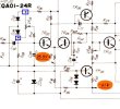
Confirm you have + and - .7 or so vdc on the offset pot ends.

9090off.jpg
 
Offset across the emitters? How do you measure offset across the emitters?

Confirm you have + and - .7 or so vdc on the offset pot ends.

View attachment 3606041
I have more around -1 and -2v on both sides of offset trimmers.

Also forgot to mention R33 smoked when the predriver went, didn't test out of spec but it was replaced as well.

And you're right I'm not really sure what I mean with across the emitters - for some reason I seem to remember finding offset there before. It's around 115-125mv fluctuating.

Also the bulb kind of strobes when powering on with the DBT.

Thank you for your quick replies :)
 
Last edited:
I am out of protect, a a trace had lifted and cracked from C05 in the top left corner, I am now out of protect.

Offset stuck at around 240ish mv in the right channel. Offset all the way down on left channel got offset to 2mv.

Update : Back in protect even with amp board removed, I have a larger problem on the protection board, I'm going to pull it, recap it and test.
 
Last edited:
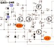
Did you replace the two diodes (D02 and D04 in my grab) Maybe a lifted/cracked pad/trace.

The top (anode) of D02 should measure + .7 or so vdc. Check it right at the diode.


1759362322648.jpeg
 
I have more around -1 and -2v on both sides of offset trimmers.

Also forgot to mention R33 smoked when the predriver went, didn't test out of spec but it was replaced as well.

And you're right I'm not really sure what I mean with across the emitters - for some reason I seem to remember finding offset there before. It's around 115-125mv fluctuating.

Also the bulb kind of strobes when powering on with the DBT.

Thank you for your quick replies :)
Very important that you get the terminology right.

Typically when you measure across a single emitter resistor or across the pair of emitter resistors, you are measuring the voltage drop from one end of the resistor to the other end to calculate bias current.

Offset voltage is measured at the junction of the two emitter resistors to ground. The junction is the output of the amplifier. Offset is how far away from zero volts that point is.

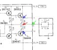
This picture is not from the 9090, this one is easier to see what I am talking about. The 9090 schematic has the parts spread out so it is not obvious what is going on.

If you measure blue arrow to blue arrow that would be voltage drop across two emitter resistors.
Measure from either blue arrow to the red arrow and it is the drop across one emitter resistor.
Measure from the red or green arrows to ground and you will be seeing the offset voltage.

Red arrow is the actual junction of the emitter resistors, the green arrow is the same point but shows where the amplifier output is on this particular circuit.
offset.jpg
 
Last edited:
Very important that you get the terminology right.

Typically when you measure across a single emitter resistor or across the pair of emitter resistors, you are measuring the voltage drop from one end of the resistor to the other end to calculate bias current.

Offset voltage is measured at the junction of the two emitter resistors to ground. The junction is the output of the amplifier. Offset is how far away from zero volts that point is.

This picture is not from the 9090, this one is easier to see what I am talking about. The 9090 schematic has the parts spread out so it is not obvious what is going on.

If you measure blue arrow to blue arrow that would be voltage drop across two emitter resistors.
Measure from either blue arrow to the yellow arrow and it is the drop across one emitter resistor.
Measure from the red or green arrows to ground and you will be seeing the offset voltage.

Red arrow is the actual junction of the emitter resistors, the green arrow is the same point but shows where the amplifier output is on this particular circuit.
View attachment 3606134
Thank you. I understood they were different but I'm a very visual learner and that helps a ton!

I will take those measurements at the diodes, but as of now I am in protect with the amp board pulled.

I am missing 56v across F01. What the frigg is going on with this thing.
 
so, nothing looks too unusual on the protection board.

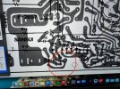
The unit will only come out of protect if this wire is removed (which is ground)… likely because that pad on protection is reading at 56 volts.

Its ground coming from the power supply board.
 

Attachments

  • IMG_0941.jpeg
    IMG_0941.jpeg
    199.1 KB · Views: 9
  • IMG_0939.jpeg
    IMG_0939.jpeg
    135.2 KB · Views: 9
Check the voltages at these two points. Those are the outputs of the power amps. Should be in the low mV range.


1759600526350.png
 
Back
Top Bottom