• The move to the new server is done. There are some software and database maintenance updates in process. This has us passing the hat around to help out. We appreciate any donations. Seriously, even a dollar helps. The payment page may be found here - https://www.audiokarma.org/support.html

Sansui 9090DB Output Problems

I get 56 and 57.2 v, I am on DBT with this guy again as I have new outputs and trimmers installed and would prefer to remain cautious. :)
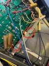
Can you show a picture where you measured that, just to be sure we are on the same page.

Good to be cautious because those voltages indicate a problem somewhere, should be low mV.
 
Can you show a picture where you measured that, just to be sure we are on the same page.

Good to be cautious because those voltages indicate a problem somewhere, should be low mV.
Yes. Here and here on other side. Neg on DMM to chassis ground.
 

Attachments

  • IMG_0963.jpeg
    IMG_0963.jpeg
    185.9 KB · Views: 13
Yes. Here and here on other side. Neg on DMM to chassis ground.
That's the spot. Definitely should not have 50+ volts there. My thoughts are that if both channels have the same issue then perhaps you are missing a power supply voltage.

Check the +56 and -61 volt supplies, they power the driver board.
 
That's the spot. Definitely should not have 50+ volts there. My thoughts are that if both channels have the same issue then perhaps you are missing a power supply voltage.

Check the +56 and -61 volt supplies, they power the driver board.
I have my -58.9 and 58.9 at the main filter caps and -61v at 2 points of the driver board and 56-58 at others. I will look over the schematic and do some poking around.
 
I have my -58.9 and 58.9 at the main filter caps and -61v at 2 points of the driver board and 56-58 at others. I will look over the schematic and do some poking around.
That sounds correct. Pull the driver board and power it up and check the offset voltage at the protection board again. Should be zero.

And how about a good close picture of the front and back of the driver board. Sometimes another set of eyeballs will spot things you missed.
 
Just realized you are the SX-780 thread as well. A little repair multitasking :biggrin: .
Now that the 780 is working maybe we can get this one sorted as well.
 
I am working on a 9090 as I write this. I have a 9090DB waiting in the batter's box. I don't know if your amplifier board is as bad as mine is, but mine is BAD. The traces have come up in so many places (which I gather is due to years of heat stress) and now my board is pretty much unsalvageable. I get it up and running, and then a few power cycles later something else goes bad. I have a new blank board coming in from Ebay (which I will have to stuff - I did not spring for the already built board), which I think is going to save me a lot of misery. I have also decided that it is no longer a good use of my time to try to save old trimmer pots. Changing them out for new with even super cheap ones tends to be profitable.
 
2SA899 was replaced with KSA1381, left channel has 150mv of offset across the emitters - unit will not come out of protect - offset trimmer has no effect on this

right channel has offset of 0 now

fun!
I am relatively new to this, but should you be checking DC offset across your emitter resistors? That would mean you are measuring a drop in voltage across those resistors rather than the amount of voltage present at the outputs (in this case, let's just say the outputs before they reach the speaker switch or the protection relay). In situations like this, I just test for DC at the output at the point where the signal enters the protection board. Maybe I am misunderstanding something. In any event, when I have excessive DC offset, I start by replacing the differential pair at the input of the driver board (TR1,2,3,4).
 
I am relatively new to this, but should you be checking DC offset across your emitter resistors? That would mean you are measuring a drop in voltage across those resistors rather than the amount of voltage present at the outputs (in this case, let's just say the outputs before they reach the speaker switch or the protection relay). In situations like this, I just test for DC at the output at the point where the signal enters the protection board. Maybe I am misunderstanding something. In any event, when I have excessive DC offset, I start by replacing the differential pair at the input of the driver board (TR1,2,3,4).

Oh, nevermind, it looks like you are checking at the input of the protection board, which would seem to be right. I saw the picture above.
 
Oh, nevermind, it looks like you are checking at the input of the protection board, which would seem to be right. I saw the picture above.
We all go through these thought gyrations, but actually writing out what you are thinking can be helpful to others, it can stimulate the thought processes of someone with a problem. Sometimes this is enough to simply help someone's understanding, and sometimes it leads directly to a solution. ;)
 
That sounds correct. Pull the driver board and power it up and check the offset voltage at the protection board again. Should be zero.

And how about a good close picture of the front and back of the driver board. Sometimes another set of eyeballs will spot things you missed.
Offset is showing zero with the driver board pulled.

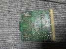
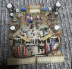
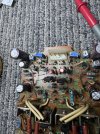
Here are pictures of the front and back of the driver board.

Had a chance to check out the power supply and the only thing that stands out is some sporadic voltage readings I’m getting at the 47uf 80v bipolar caps. Definitely going to pull test and post an update in the morning.
 

Attachments

  • IMG_0988.jpeg
    IMG_0988.jpeg
    240.1 KB · Views: 6
  • IMG_0987.jpeg
    IMG_0987.jpeg
    221 KB · Views: 6
Thanks for the pictures. I see a couple of things.

Could be the light or the angle but those resistor leads may be touching?

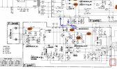
The other blue box. (should have made it red) Pretty sure you have that transistor oriented wrong. :(

9090dr1.jpg
 
Thanks for the pictures. I see a couple of things.

Could be the light or the angle but those resistor leads may be touching?

The other blue box. (should have made it red) Pretty sure you have that transistor oriented wrong. :(

View attachment 3609986
I hope not! Here are some better pics. The transistor orientation for that pre driver are the inverse of each other.

No leads touching fortunately.
 

Attachments

  • IMG_0991.jpeg
    IMG_0991.jpeg
    240.4 KB · Views: 5
  • IMG_0992.jpeg
    IMG_0992.jpeg
    225.5 KB · Views: 5
Also still getting 57-58v across both fuses on protection circuit, and on pins 15 and an unlabeled pin that I thought was ground before. May be completely wrong.

Attaching pictures.

I’m out of protection with this wire removed. Attaching picture of that as well, I think I may have already added it previously.
 

Attachments

  • IMG_0993.jpeg
    IMG_0993.jpeg
    210.6 KB · Views: 3
  • IMG_0994.jpeg
    IMG_0994.jpeg
    156.3 KB · Views: 3
Also still getting 57-58v across both fuses on protection circuit, and on pins 15 and an unlabeled pin that I thought was ground before. May be completely wrong.

Attaching pictures.

I’m out of protection with this wire removed. Attaching picture of that as well, I think I may have already added it previously.
On the first picture you have two spots circled and on the second picture you show one wire. I think the black wire comes from the unlabeled pin, correct?
I think the red box is the unlabeled pin.

With that unlabeled pins black wire removed from ground at the power supply board you have removed the ground reference from the sensing circuit.

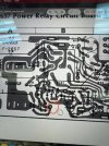
I believe you but at first glance I don't see how pin 15 can have 57 volts on it. We will worry about that one later, bigger fish to fry with the 57 volts at the fuses.


9090prot2.jpg
 
I hope not! Here are some better pics. The transistor orientation for that pre driver are the inverse of each other.

No leads touching fortunately.
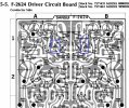
My board layout shows them as 180 degree opposites. Comparing to the schematic the service manual board layout is wrong for TR02. It should be the same as TR01 BCE from top to bottom. So you are good to go.

9090drv1.jpg
 
Lets do a reset.

Put the black wire from the protection board back.

Remove the driver board and check the voltages at the fuses.

If they are near zero (low or no mVDC) the protection circuit should blink the lights and close the relay.
 
On the first picture you have two spots circled and on the second picture you show one wire. I think the black wire comes from the unlabeled pin, correct?
I think the red box is the unlabeled pin.

With that unlabeled pins black wire removed from ground at the power supply board you have removed the ground reference from the sensing circuit.

I believe you but at first glance I don't see how pin 15 can have 57 volts on it. We will worry about that one later, bigger fish to fry with the 57 volts at the fuses.


View attachment 3610048
Sorry it was too early and I wasn't thinking, I'm not sure why I thought that second picture was relevant here, it's two grounds that I had to desolder to get a better look at the protection unit.

Or the first picture really, it's just another ground wire.

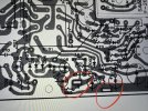
I've circled where the ground wire comes from the PSU board and goes into the protection circuit. Not sure what it is referred to as, and that is where I am also getting around 57-58v.

Will do a reset and take measurements as soon as I am back home! Thanks guys!
 

Attachments

  • IMG_0995.jpg
    IMG_0995.jpg
    181 KB · Views: 2
Oh geez, that is confusing.
There are lots of well know and documented errors in service manuals. This may be/probably is one of them? I don't have much under the hood time with the DB versions of these.

A lot of straight 8080's and 9090's which are a little different.
 
Back
Top Bottom