• The move to the new server is done. There are some software and database maintenance updates in process. This has us passing the hat around to help out. We appreciate any donations. Seriously, even a dollar helps. The payment page may be found here - https://www.audiokarma.org/support.html

Sansui 9090db

bbpdoubleb

Member
9090db sansui


Hello All, my sansui 9090db smoked awhile back, tore it down had some bad outputs and the F-2624 board had bad resistors, caps, transistors. Installed all new 8 outputs, put all new resistors,caps and transistors on F board, went thru protection circuit (bad resistor) reason it never turned green even all the years it was working. Cut the grounding wire out of it right next to the relay (this would short the speaker outputs,bad idea by sansui). Anyhow got all together and without the F board in all comes on fine and comes out of protection and has green light----power down and plug the F board in and power up and the 2, 10 amp fuses on power board blow. Any Ideas?
 
Register to hide this ad
First thing I'd do is double check the cap polarity. Sansui's known for wrong pointers on the schematic and on the boards. Best bet is to replace one at a time, note the polarity of what came out, and match it.

This one should be good as an example:

F2624_FRONT_1.JPG


Double check real close for solder bridges and missed or cold connections while you're at it. Easy enough to do if you're tired or in a hurry.

Also, I do believe it is possible to plug the boards in one off on the pins. That'll certainly screw things royal.
 
Yep, pretty much what is happening is something is short circuiting in both Main DC rails which is in turn blowing the two 10amp fuses.

So, as skizo says, could be a driver board mounted one pin off, wrong polarity cap, wrong polarity transistors in the wrong place....
Could be a number of things...

You will have to go back and meticulously check your work....

What wire did you just "cut off"?
 
yep, it could be one pin off and if so the thin ground trace on the underside of the power supply board will be burned off...

BTW Skizo, that looks like a "resurrection" driver board you've got right?
 
Yes I understand and I know about the 1 pin off but had it on correctly 3 times and 3 sets of fuses, the jumper wire you do away with is on the protection board, it is right next to the relay this grounds out the speaker outputs when turned off---if you have a relay go bad and contacts stay closed (stuck) things will FRY! when u turn on(bad idea that sansui had) so I heard about this from a guy in the KC area and other places. We are taking the board back to the bench and hope we find something! Thanks Guys if anyone else has any ideas let me know!
 
Yup ... but I do believe it's an official Sansui substrate. Could be wrong ... either way, should be good for a polarity check.

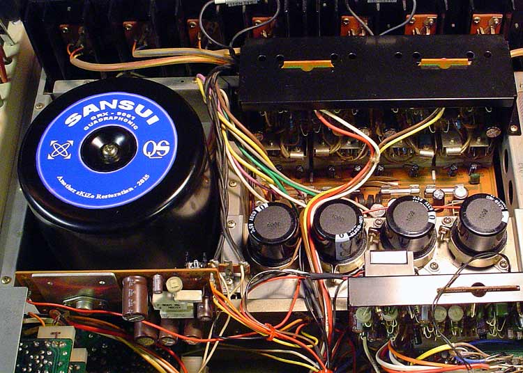
That board shows up all over the place. Here's a couple, looking right at home in my restored QRX-9001 ...

completed-xformer.jpg
 
One pin off won't blow the outputs and I doubt cap polarity would either. You may not have fixed the original fault by just replacing the outputs. You also need to check the driver transistors, emitter resistors for the outputs and other incidental parts on the driver board. If the bias trimmers are bad, the outputs won't last long.

Do you have a dim bulb tester? You should be using it here.

- Pete
 
Believe it or not Pete have never used a dim bulb tester, just our flukes, what is the basics on a dim bulb tester? Bill
 
It puts an incandescent light bulb in series with the power supply to limit current flow through the amp. The brightness of the lightbulb gives a visual representation of how much current the amp is drawing. The lower the wattage of the bulb, the more resistance in the input circuit.

A normal amp will have a surge of power as the filter caps charge then the light will dim to almost nothing at zero volume. If it stays bright, you have a problem.

It's a very simple tool. There are lots and lots of tutorials on how to build one. There's one in the Sansui FAQs.

- Pete
 
My dim bulb's better than your dim bulb ... <G>

dimbulb-002.jpg


Not seen is an old power strip with several different wattage bulbs loaded up in adapters. All that screwing is kinda hard on us old guys, doncha know ... ;-}
 
My dim bulb's better than your dim bulb ... <G>

dimbulb-002.jpg


Not seen is an old power strip with several different wattage bulbs loaded up in adapters. All that screwing is kinda hard on us old guys, doncha know ... ;-}

I see you have to remind yourself that its a DBT Skiz..:D
 
Er ... Uh ... was that a test?

Us dim bulbs gotta post notes to get through the day, eh. Besides ... I paid good money for that label machine! <G>

label-machine.jpg
 
Without looking at the schematic, I figure that's a fuseable resistor ... those are meant to burn to protect the more sensitive bits. Light blue or gray matte finish?

That said, they're also a bit of a time bomb, as they break down with heat over time and can blow even if nothing else is wrong. It's HIGHLY recommended that ALL those be replaced.

You'll notice they're set away from the board. That's necessary as they DO get HOT in normal operation. Make sure you keep the spacing when replacing. Good idea to crimp the legs on the new ones so they can only set down so far.

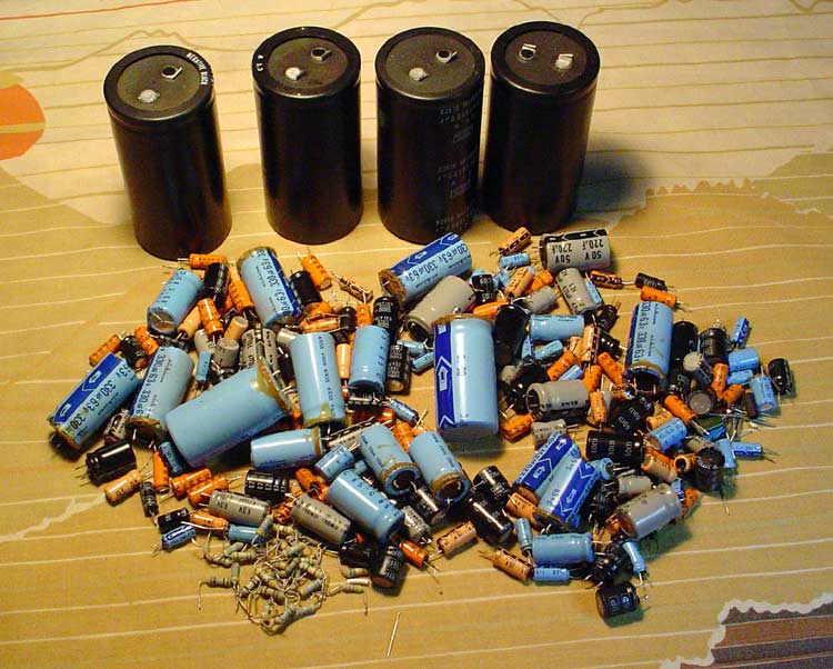
Here's the discard pile from my 9001 ... all those resistors are fuseable.

pile-of-caps.jpg


The values are usually hard to read, so you WILL need a schematic to figure out what you need, unless some kind soul here has a list ...
 
Thx SkIzo, yes it is light blue, I do have the schematic and pictures of the boards with a listing of the parts and values associated with each (beginning to not trust these---wrong listings, values,things that are on the board but not listed in them etc..) there are 2 of these side by side R-15 and R-16. Needless to say it wont come out of protection with this blown but was coming out of protection before we put the driver circuit board (F-2624) in and blew the 2- 10 amp fuses. We are in the process now of checking all cap polarity etc.. on the driver board, was wondering if the fuses blowing would knock this resistor out? Or if it blowed and caused the fuses to blow? Getting P----- OFF! Thx
 
Totally possible ... as mentioned earlier, they're made to act as internal fuses, and ARE there to protect the more expensive bits. I'd replace them all.

There's probably only three or four different ratings, and you can use ½ watt metal film resistors instead. Those will provide the same level of protection and hold up better to the heat.

Best bet is to just read the component number on the board and match it to a value on the schematic and see if you can convince yourself that the resistor stripes match. Don't try to read them under florescent lights as those lie.
 
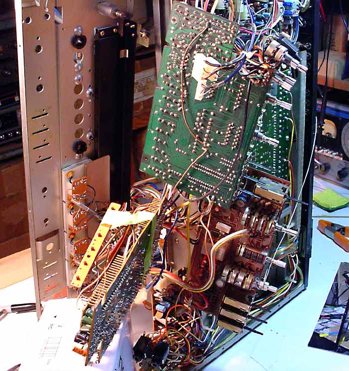
This should make it look a bit easier ...

stage-two-teardown.jpg


Strangely enough, the power board was the easiest to get to on my 9001 ... I could do everything needed with the board still mounted in (what was left of) the chassis ...
 
Back
Top Bottom