• The move to the new server is done. There are some software and database maintenance updates in process. This has us passing the hat around to help out. We appreciate any donations. Seriously, even a dollar helps. The payment page may be found here - https://www.audiokarma.org/support.html

Sansui 9090db

Unread Today, 11:15 AM


sKiZo's Avatar
sKiZo sKiZo is online now

Audio Puree-ist


Join Date: Apr 2009

Location: 42.96°N 85.67°W (Elev. 620 ft)

Posts: 8,162


Without looking at the schematic, I figure that's a fuseable resistor ... those are meant to burn to protect the more sensitive bits. Light blue or gray matte finish?

That said, they're also a bit of a time bomb, as they break down with heat over time and can blow even if nothing else is wrong. It's HIGHLY recommended that ALL those be replaced.

You'll notice they're set away from the board. That's necessary as they DO get HOT in normal operation. Make sure you keep the spacing when replacing. Good idea to crimp the legs on the new ones so they can only set down so far.

Here's the discard pile from my 9001 ... all those resistors are fuseable.


The values are usually hard to read, so you WILL need a schematic to figure out what you need, unless some kind soul here has a list ...

__________________
DAILY DRIVER > Sansui QRX-9001, Latino ST120, Maverick D1+, dbx 200x2, dbx 3BX, Carver C9, Technics SH9010, Sony GT710hd, Mitsubishi DP-EC10, dbx Boombox, McIntosh XR16 w/EQ104, Bose 161, Gekko GK1114, Art DJpre II, Magnum FM Sleuth w/Dynalab FM3, Bach Media HTPC, dbx SNR-1

Reply With Quote Multi-Quote This Message Quick reply to this message


#17 Report Post

Unread Today, 01:31 PM


bbpdoubleb bbpdoubleb is online now

AK Member


Join Date: Sep 2015

Good deal, my protection board has to be got to from bottom and the bracket that holds it in is a real sob! 3 little screws that hold it in are a bear to get to without tearing completely down
 
looks like you're a bit far in to change tack. From memory it's a lot easier to work on that board from the top with the tuner tray removed; that way the 3 screws don't need to come out...
 
Keep us posted on what all goes down.

PS: ... #21 has to be one of the stranger posts I've seen on the board. Whatever you did, don't do it again ... <G>
 
Hello All, installed R-16 on protection board, comes out of protect and lights up green without F2624 board in, we took the board to lab and double checked all transistors solder joints etcc..Found 1 bad Diode D16 (didn't make any difference) Plugged in DBT and installed board and still have problem, bulb lights up bright and then goes dim, bright and then dim. Take board out and comes up fine on DBT and comes out of protection?? We don't know what the next move is, any ideas?? Thx
 
Make sure the bias adjustment trimmers are turned so that bias is at minimum, then try it with DBT again.
 
Does the DBT continue to cycle between bright and dim or does it stay dim after the start up surge? What wattage bulb are you using?

Also, what is the DC offset? There is a blue and a grey wire coming off the bottom of the power supply board. These wires carry the left and right channel audio signal from the driver board to the protection board. You can measure it while it's in protection by connecting your voltmeter each of these wires and chassis ground. This will tell you a lot about what's going on in the amp.

- Pete
 
Make sure the bias adjustment trimmers are turned so that bias is at minimum, then try it with DBT again.

^ ^ ^ +1

Also be aware that the trimmers are VERY sensitive, and it doesn't take much to tweak them into dangerous territory. Mark where they are now, and try to reset as close as you can, then meter them fast to get them back in range. If you're gonna move them anyway, I'd also take the opportunity to clean the wipers well before proceeding as they do get the crust of ages over time.

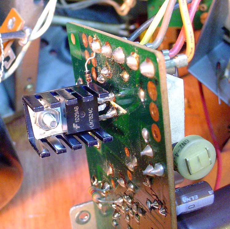
I did a cute lil mod on my QRX 9001 recommended by the gurus, adding a 25v regulator to the power board that supplies the F2624.

25v-regulator-007.jpg


Not sure if the same would help (or even be necessary) on the 9090db, but well worth checking, and well worth the effort if it applies. With the 9001 especially, it's all about protecting those unobtanium ICs ...
 
bulb lights up bright and then goes dim, bright and then dim

I had what looks like a similar problem a few months back. Turned out to be a bad solder joint on one of the TR13/14 mounted thermal tracking diodes (or perhaps transistor maybe in your case). It was causing the current limiting network to operate...
 
The DBT just continues to go from bright to dim, bright to dim--left it plugged in for 10 seconds, using a 60 watt bulb--------we will measure the DC offset in awhile (what should it measure pete?) voltage wise? Thx Bill
 
Cant get any voltage measurements to chassis ground on blue or gray wire, heard a faint click once and had -46v on the blue for a bit, but not on the gray. Relay is kicking in fine and going green before I ever tested the 2 wires to ground??
 
Okay, we put the f board in turned amp on with DBT for a few seconds and had 10.7 to 10.9 volts on each (blue and gray to ground)
 
You have driver board issues if you are seeing 10 volts on those wires. It should be near zero volts.

Start by checking the driver transistors and related components. The drivers are the ones mounted on the heat sinks. Look for open resistors and blown diodes related to those transistors. Also check the output transistor emitter resistors. They are the ceramic resistors on the power supply board.

- Pete
 
Okay Pete will do, we did pull all the driver transistors and the other transistors on the f2624 and double checked those Saturday---will check the emitter resistors on power supply board. Thx Bill
 
One thing before we dive into the power supply board, on it the 2 fuses (10 amp) that we blow when plugging in F2624 board (not now with DBT)that are coming off the secondary side of transformer (2 purple wires) , the only things according to schematic between them and the next set of 10 amp fuses which don't blow is 2 thin wafer like capacitors (look like small pennys) c-13 and c-12 and then DO1 and DO2 diodes that look like a U shapped bracket with 2 legs going into board off each, from there it goes to the 2 main 12000, 63V caps with red and white wires (suppose to have 50v on them)coming back to board where the second set of fuses are (that don't blow) any ideas??? Thx Bill
 
Wasn't that the original problem, those fuses blowing? Have you checked the rectifier diodes? The ones on those U bridges. Also make sure you wired the filter caps properly.

As a side note, 63v is a little low for those filter caps. I believe the originals were 70v.

- Pete
 
Never had the caps unwired they are factory wired with solid bridge wire on top connecting the 2 with big brown resistor on each and red wire from 1 cap and white wire from other cap that go to board next to the second set of fuses (that don't blow without DBT), I am second owner and they are 80v, and yes this was the problem after it smoked one night months ago and we went thru and put new outputs in it and reworked all componets on the f2624 board, all outputs test good (now that we have DBT and not frying any anymore) and we have went over the F2624 board 3 times. Could those rectifier diodes cause the 2 fuses to blow?? Thx Pete
 
Yes they could blow the fuses. They don't typically fail, but considering the symptoms, I'd check them.

- Pete
 
Back
Top Bottom