• The move to the new server is done. There are some software and database maintenance updates in process. This has us passing the hat around to help out. We appreciate any donations. Seriously, even a dollar helps. The payment page may be found here - https://www.audiokarma.org/support.html

Sansui AU-11000 new project

I used to own a AU-9900, that had all the wire connectors removed and the wires soldered to the pins as in your picture. But not the unbelievable soldering of those larger connectors, like the one next to the relay - that really is ridiculous. :yikes:


It seems back then(?), or more recently there was a misguided belief that you should solder all the connectors to avoid channel drop-outs and other connection problems with these amplifiers. I went through my amplifier and put back all the connectors, however in the mean time the connectors have been discontinued and as far as I know are NLA unfortunately.
Thank you, John. I tried to find the connectors, but had no success. Now I am working on the F-2580 board and the F-2581, but I need to stop because I ordered some components.
Also, the F-2580 is an old board full of jumpers and cuts on the tracks. Also, if you compare with the new board revision, the position of the capacitors does not match. Soon, I will post a picture
 
The soldered connections are not factory. I have seen this before, efforts by a "technician" to solve intermittent problems caused by something else, or it could have been caused by a bad crimp on the connector, which should have been properly fixed. You can get Molex connectors to replace them.
 
Thank you, John. I tried to find the connectors, but had no success. Now I am working on the F-2580 board and the F-2581, but I need to stop because I ordered some components.
Also, the F-2580 is an old board full of jumpers and cuts on the tracks. Also, if you compare with the new board revision, the position of the capacitors does not match. Soon, I will post a picture
I sourced them. I will have a look at the part numbers later today.
 
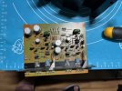
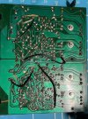
This is my F-2580 board. See the jumpers and cuts in the traces. I believe that was an old version.

IMG_1401.jpg

Also, you can see the top of the board, which is different from the new one

IMG_1395.jpg

Now this is the new F-2580 version:

Screenshot 2025-09-08 084117.png
 
Another thing is that there is no way to restore this board without removing the front of the chassis:

1757302037270.png
 
I looked through my box of Molex connectors. Looks like I could not find ones with the same pin spacing. I think what I did was use these and cut every other pin. So here are a few of the part numbers to get you the correct series.
For the cable mount connectors I didn't have a crimping tool so I bought board mount sockets and soldered the wires to the pins:
09-48-3044 (4 pos)
09-48-3084 (8 pos)
Then I did buy at least one cable mount connector and some contacts:
22-01-3127 (Housing, 12 contacts)
08-50-0114-C (contacts)
PCB Mount Headers:
22-27-2081 (8 pins)
22-27-2101 (10 Pins)
22-27-2121 (12 pins)

There were a few more but this gets you into the series. These were for the output boards, I think. Some moron cut them off, just like on yours.
 
Last edited:
I looked through my box of Molex connectors. Looks like I could not find ones with the same pin spacing. I think what I did was use these and cut every other pin. So here are a few of the part numbers to get you the correct series.
For the cable mount connectors I didn't have a crimping tool so I bought board mount sockets and soldered the wires to the pins:
09-48-3044 (4 pos)
09-48-3084 (8 pos)
Then I did buy at least one cable mount connector and some contacts:
22-01-3127 (Housing, 12 contacts)
08-50-0114-C (contacts)
PCB Mount Headers:
22-27-2081 (8 pins)
22-27-2101 (10 Pins)
22-27-2121 (12 pins)

There were a few more but this gets you into the series. These were for the output boards, I think. Some moron cut them off, just like on yours.
Hi @dr*audio,

Thank you very much for the info, really appreciate.

This is the way that is right now, the board has the sockets, but the cables are soldered to the pins
 
I think the best you can do is MJE15032C and MJE15033C. They are 30MHz, but you can't get 60MHz parts and it won't make a difference to performance.
 
KTB1369-Y Audio Transistor PNP -180V 2A
KTD2061-Y Audio Transistor NPN 180V 2A

2SA1837G-TF3-T
2SC4793G-TF3T

Profusion Ltd has them in UK .
 
I just received the Sansui Au-11000 beautiful Amplifier, which I intend to restore. Below is a picture of it

View attachment 3585578

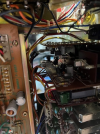
I was so happy until I opened it, then my disappointment, this must be one of the first units produced. If you look at a similar AU-11000 or Au-9900, all of them have connectors to integrate one board to the other; unfortunately, this one does not have them, as you can see in the next picture:

View attachment 3585582

This will take my job to another level. I will have to disconnect all the cables to remove the boards to work on them. Not to mention that every capacitor is tightly glued, which is another time-consuming task to clean all the PCBs of that glue.
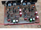
Also, the board F-2568 is soldered to the F2567, so I have to work with the 2 boards attached, as you can see:

View attachment 3585588

Most of the caps on the board F-2568 are replaced already, missing 2 caps that I have to clean the glue, then I will replace the transistors 2SC1313 with KSC1845, and the board F-2568 will be done.

I will post the progress and the difficulties found.

What will you use to get the glue off?
 
Glue removal?....I use acetone as in nail polish remover...
wooden cutical sticks from the dollar store also helps scrape the glue after softening w/o damaging ...
 
I think the best you can do is MJE15032C and MJE15033C. They are 30MHz, but you can't get 60MHz parts and it won't make a difference to performance.
I used the MJE15033/34 pair, but I have an unusual issue, which I will describe in another post, and need some help on that.
 
KTB1369-Y Audio Transistor PNP -180V 2A
KTD2061-Y Audio Transistor NPN 180V 2A

2SA1837G-TF3-T
2SC4793G-TF3T

Profusion Ltd has them in UK .
Thank you very much, but I am in China, and the best for me is local or Japan.
Checked on the local supplier, they have it in stock.
 
Let me try to explain what happened:
The amp was restored, all caps, and suspected transistors replaced, bias and the DC offset adjusted, then I connected my oscilloscope, and got a weird reading, the sine was not perfect, so I tried to adjust it, but my arm just touched the probes and dislodged the ground one from the board F-2580 (the driver board), and it touched the collector of one of the driver transistor. This gave me a short between the collector and the ground earth of the oscilloscope. All transistors in the channel burned, including the output TO-3 Sanken ones; it stopped in the 7A fuses in the F-2567 board protecting the power supply.
I removed the F-2580 board and replaced all transistors in it, checked all diodes and resistors. I could find a pair of used Sanken here in China, but I made a mistake. I should have tested the fix first on that channel, but I decided that it was better to also change the other channel components to avoid imbalance. After that, I connected the DBT replaced the fuses, and powered up the amp; it powered up with no issues, so I went ahead and started to set the bias, which I did without any problem, but I can not set the DC offset. The lower V that I can get is 1.7V DC in both channels, and with this, the relay will not engage.
I have tested everything, checked the transistor's pinout, diodes, and resistors, as I said, before the incident, all were working fine, now the 2 channels are the same, I can not set the DC offset. The only thing that I can think about is wrong transistors, because I replaced the 2 sides with the same components.

I would appreciate it if somebody has another idea, because maybe the solution is in front of me and I can not see it.
Thnak you all
 
Let me try to explain what happened:
The amp was restored, all caps, and suspected transistors replaced, bias and the DC offset adjusted, then I connected my oscilloscope, and got a weird reading, the sine was not perfect, so I tried to adjust it, but my arm just touched the probes and dislodged the ground one from the board F-2580 (the driver board), and it touched the collector of one of the driver transistor. This gave me a short between the collector and the ground earth of the oscilloscope. All transistors in the channel burned, including the output TO-3 Sanken ones; it stopped in the 7A fuses in the F-2567 board protecting the power supply.
I removed the F-2580 board and replaced all transistors in it, checked all diodes and resistors. I could find a pair of used Sanken here in China, but I made a mistake. I should have tested the fix first on that channel, but I decided that it was better to also change the other channel components to avoid imbalance. After that, I connected the DBT replaced the fuses, and powered up the amp; it powered up with no issues, so I went ahead and started to set the bias, which I did without any problem, but I can not set the DC offset. The lower V that I can get is 1.7V DC in both channels, and with this, the relay will not engage.
I have tested everything, checked the transistor's pinout, diodes, and resistors, as I said, before the incident, all were working fine, now the 2 channels are the same, I can not set the DC offset. The only thing that I can think about is wrong transistors, because I replaced the 2 sides with the same components.

I would appreciate it if somebody has another idea, because maybe the solution is in front of me and I can not see it.
Thnak you all
The driver transistors shouldn't cause that offset if installed correctly. Check the continuity of the ground between the power supply and the driver boards. Maybe a trace burned.
 
The driver transistors shouldn't cause that offset if installed correctly. Check the continuity of the ground between the power supply and the driver boards. Maybe a trace burned.
Yes, you are right, but I had to start testing from the top; in the end, the responsible should be TR01 and TR03. I am talking only to the left channel. I have tested the ground, and it is interesting that in the Sansui, the chassis is not the ground reference. I was thinking about the 150K resistor before the VR01, but I am not sure because the issue is in both channels, and I did not replace them, but I replaced the transistors. I have the V measurement of them looks normal, but still the VR01 goes from a minimum of 1.7V to 3.7V DC on post 17 on F-2567 before the relay, then it will not engage with that voltage. The right channel behaves the same. This is weird.
 
Back
Top Bottom