• The move to the new server is done. There are some software and database maintenance updates in process. This has us passing the hat around to help out. We appreciate any donations. Seriously, even a dollar helps. The payment page may be found here - https://www.audiokarma.org/support.html

Sansui AU-11000 restore extent?

It would be rare (but not impossible), for the silk screen to be wrong, but from what you say it seems like they are in backwards.

According to the Sansui provided pinout info in the SM, 2SA726 are BCE (flat towards you, legs down), whereas - as you suspect, KSA992 are ECB.

The only datasheet I can find from a search for '2SA726' is the 2SA720 datasheet, which says ECB. :(

If I have doubts like that I just use my Peak Transistor Tester to identify the pinout - problem solved.
All correct.
I did buy the nicer/newer Peak device on the advice of the folks here.
So happy with this tool, should have bought one years ago.

The 992's are in correct.

The only other observation I made is the +63v and -65v coming from F-2567 power supply board is +55v/-55v. 20% down
The regulators TR601/602 (2SC1124/2SA706) have been replaced by MJE15032/MJE15033 respectively.
TR604 (2SA726) has been replaced by KSA992.
Fully recapped with low ESR Nichicon, all glue cleaned off.
The input to the regulator is down, +57V/-58V, respectively.
If it was getting overloaded, the regulators should be getting warm/hot, they are cool to the touch.
The 2SC1124/2SA706/2SA726 tested OK on the Peak meter, though the legs are completely blackened with oxidation.

There is a 13V (1 watt?) zener, RD13E at ZD-601, can the Peak meter check if it is woking as a 13V Zener, or just that it is a zener?

The +35v is on spec.
The dual +/- 55v for both main rails is also on spec.
Input line voltage is 120VAC.
 
The correct pinout can of course be determined by comparing the schematic to the trace destinations, if the Emitter for example is supposed to be connected to R? And the collector to C?, that is how I check my work before powering up.

Although schematics have been wrong, it is more likely correct than the silk-screen artwork. I suspect that you’ve already considered this but throwing it out there anyway.
The silkscreen is correct.
The KSA992's are in correct.
There's something else is going on.
 
Update on the rebuild:
99% done. Main caps are the only item to install, waiting on delivery.

The offset (both channels) is the only remaining an issue: stuck at ~400mv.
One commonality the two channel share is the + 65v / -67v from the F-2582 supply for the driver board.

When I measured: I was getting +56v / -58v which is the correct voltage for the AU-9900.
I suspected the 13V zener. When changed, the measurement rose to +57.9 / -59.7
8 volts short of spec, with no positive effect on offset control.

On F-2582 supply for the driver board, I changed TR601 (2SC1124) and TR602 (2SA706) to MJE15032/33 as these devices are known to be noisy (which they were.)

Should I try the KSC2690/KSA1220 combo? I'm running out of ideas.
The alternate devices Sansui has listed for this location: 2SD356/2SB526.
 
Not sure where you're at on this, but I don't know if you lifted the jumpers from the 2567 (or 2582?) board & making sure the voltage is correct leaving that board? If it's good leaving then you can just concentrate on what's dragging it down on the amp board. Are the voltages to the 2568 OK?
 
Not sure where you're at on this, but I don't know if you lifted the jumpers from the 2567 (or 2582?) board & making sure the voltage is correct leaving that board? If it's good leaving then you can just concentrate on what's dragging it down on the amp board. Are the voltages to the 2568 OK?
Voltage into the regulators (TR601/601) are at the specified +67v/-69v. Voltage leaving the devices are +57.9v/-59.7v.
This is the same voltage seen at the driver boards. All jumpers are in their correct positions.
I have not tried unplugging the driver board feed to see if the board is loading it down.
TR601/602 are cool to the touch, if they were being stressed, they should be warmer than they are.
 
Right......just thinking that isolation is always good. If you pull the jumpers to the driver board & the voltages jump to where they should be then you put the possible regulators issue to bed.
 
Update on the AU-11000 rebuild: Just back at it from clearing out the Pre-Christmas rush of customer repairs.
Found stock on Nichicon Super-Through main caps! Thanks Hyperion. All good there.

The rebuild was almost complete until I got to the driver board (F-2583). When I changed the notoriously troublesome 2SA726's at TR1, 2, 3 & 4 for KSA992(F) the bias went off scale and took out the fuses supplying the driver board voltage (both channels). Whatever I did wrong, I did it to both channels!

The power supply for the driver board is the F-2583, the power supply for the driver is F-2582.
When this combination is used, the driver voltages should be +48v & -52v according too the factory service manual.

What I am getting is +58v & -60v.
If I had the older F-2567 driver and the F-2580 supply board, the voltages are higher: +63v & -65v.
But I'm not even sure this (power supply voltage) is my problem.

Should I be chasing the power supply variation?
After I rebuilt it, it was working, then I started into the driver board rebuild and the bias problem came up.
Or was that just coincidence?

I've removed every semiconductor on the driver board and tested them individually on the PEAK tester, including the 8 outputs.
Caps are all new and polarity double checked. Resistors were measured (though in circuit) good so far.
Cleaned and inspected the board under glass looking for fractured traces... it all looks good.
I'm missing something obvious?

After finding so many noisy transistors, I thought I had this licked. So close, and yet so far.

Any advice would be welcome.
 
I don't know if you're looking at the same SM I am (AU-9900/11000 combined), but mine shows the 2582/2583 variation as the last schematic but it's for the 9900 (page 22?). Compare the voltages on the transformer 2ndaries on the schematics.
 
I don't know if you're looking at the same SM I am (AU-9900/11000 combined), but mine shows the 2582/2583 variation as the last schematic but it's for the 9900 (page 22?). Compare the voltages on the transformer 2ndaries on the schematics.
One leg on the red pair seems too low. I'll try an open circuit measurement
 
You didn't put the 992's in backwards did you?

726's are BCE
992's are ECB
I'm following the nomenclature on the board. (which has been known to be wrong) Tracing the footprint out is the next logical step.
'Cause it was the moment I swapped those little critters that my troubles began.
 
You didn't put the 992's in backwards did you?

726's are BCE
992's are ECB
In practise this means the 'D' shape of the transistor is opposite to what it was before with the old transistors. (With the bias setting symptoms, I am finding it hard to believe it is anything else). If you are following 'D' shaped silk screened markings on the board - the transistors are installed incorrectly.
 
Last edited:
The power supply for the driver board is the F-2583, the power supply for the driver is F-2582.
When this combination is used, the driver voltages should be +48v & -52v according too the factory service manual.

What I am getting is +58v & -60v.
If I had the older F-2567 driver and the F-2580 supply board, the voltages are higher: +63v & -65v.
But I'm not even sure this (power supply voltage) is my problem.

Should I be chasing the power supply variation?

My point was that, & this is just in regards to the voltage, the schematic you're seeing for the 2582/2583 boards are those for the 9900. I know it doesn't specify it, but if you look at the transformer 2ndary leads on the schematic it shows 45v & 45v for the red leads......33v & 33v for the purples. The 11000 has 50v/50v & 39v/39v, respectively. The fact that you have the correct +67v/-69v before TR601/602 tells us the driver voltage (+63v/-65v) is getting loaded down after the regulators. I'd be willing bet that if you find the bias issue on the driver board that your voltages will be close to correct.
 
I don't know if you're looking at the same SM I am (AU-9900/11000 combined), but mine shows the 2582/2583 variation as the last schematic but it's for the 9900 (page 22?). Compare the voltages on the transformer 2ndaries on the schematics.
With a line voltage of 118VAC White (CT) measured to each Red leg is 51VAC (45V spec) White to each yellow leg is 31VAC (30V spec) unloaded.

Discrepancies in the parts list for F-2583 vs what is mounted on the board:
Parts list for R13, 14, 15 & 16 is specified for 47Ω, the schematic says 10Ω What is installed is 10Ω
Parts list and the schematic for R19 & 20 is 820Ω, a 1KΩ is installed.

Pinout for KSA992 has been verified, they are correctly installed and test good on the PEAK device.
 
The power supply for the driver board is the F-2583, the power supply for the driver is F-2582.
When this combination is used, the driver voltages should be +48v & -52v according too the factory service manual.

What I am getting is +58v & -60v.
If I had the older F-2567 driver and the F-2580 supply board, the voltages are higher: +63v & -65v.
But I'm not even sure this (power supply voltage) is my problem.

Should I be chasing the power supply variation?


My point was that, & this is just in regards to the voltage, the schematic you're seeing for the 2582/2583 boards are those for the 9900. I know it doesn't specify it, but if you look at the transformer 2ndary leads on the schematic it shows 45v & 45v for the red leads......33v & 33v for the purples. The 11000 has 50v/50v & 39v/39v, respectively. The fact that you have the correct +67v/-69v before TR601/602 tells us the driver voltage (+63v/-65v) is getting loaded down after the regulators. I'd be willing bet that if you find the bias issue on the driver board that your voltages will be close to correct.
The service manual does list both the AU-9900 and AU-11000 schematics separately.
The manual also shows both F-2580/F-2583 driver boards, F-2567/F-2582 power supply boards, each being interchangeable (however the wiring layout is very different)
For this reason, the manual suggests staying with whatever version was originally installed for ease of replacement.

I found 51VAC on the reds, 31v on the yellow and 40.5v on the purple. I believe you are correct, the problem is unlikely to be on the power supply board.
 
In practise this means the 'D' shape of the transistor is opposite to what it was before with the old transistors. (With the bias setting symptoms, I am finding it hard to believe it is anything else). If you are following 'D' shaped silk screened markings on the board - the transistors are installed incorrectly.
I followed the traces marked "BCE", the nomenclature is correct.
I measured the KAS992 on the Peak meter to make sure I correctly identified each pin, then marked the base side of the device with a silver sharpie.
I didn't make that mistake, they were installed correctly.

I am baffled. I'm going to pull the outputs one more time, maybe I made a mistake reassembling the first time I checked them.

Is there a why to check the driver board with the output transistors unplugged?
 
So here's where I'm at:
TR08 Emitter 58.5V, Base: 58V, Collector: 45v E to B= 0.5v: off
TR06: Emitter -57V, Base: -56.5V, Collector: -2.7v E to B= 0.5v: off
TR12: Emitter -2.7V, Base: -2.1, Collector: 1.5v E to B= 0.6v: off
TR02: Emitter 0.98v, Base: 0.38V, Collector: -56.3v E to B= 0.59v: off

The issue concerning me is the discrepancy in the documentation and what is on the board: R13, 14, 15 & 16 (TR02 & 04 Emitters) are listed as 47Ω. 10Ω is what is mounted on the board.
R19 & 20 (TR02 Collector) are listed as 820Ω, 1KΩ is what is mounted on the board.
 

Attachments

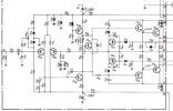
  • F-2583 diag.jpeg
    F-2583 diag.jpeg
    57.6 KB · Views: 8
Solved! By measuring the 2SA726's that came out, I noticed they were of very high gain Hfe >500.
The KSA992's where swapped out for the highest gain I could find in my stock: Hfe = 490
An Hfe of 360 simply would not work.
Help me understand that one.
 
That is wild. And there's no indication in the SM about the higher gain on those 2SA726?

I tried to find a 2SA726 PDF to see if they were sorted with no luck, just listed as Hfe >55
 
That is wild. And there's no indication in the SM about the higher gain on those 2SA726?

I tried to find a 2SA726 PDF to see if they were sorted with no luck, just listed as Hfe >55
When I got the notice from Mouser KSA992 were being discontinued, I bought 100 and sorted them so I could source matched pairs when needed.

Hfe ranged from 320 > 490.

While I do not understand the why, I'm just glad I was finally able to put this job to bed.
I changed out every capacitor for low ESR (and film caps where applicable) and all of the known problem transistors, retaining as much of original silicon as possible.
The driver board was the last to be rebuilt. I've been fighting this bias issue (on and off) for over a month.

This is going to be my new test mule for the workshop, it has to be right.
I think the reason I got it so cheap, is the case and front panel are pretty beat up.
The prior owner was a smoker, it stunk, all the knobs were stained orange.
Some of the controls are bent, but they work smoothly, so I didn't risk trying to unbend them.
It won't win any beauty contest, but it's new purpose is being a critical part of my test equipment.

So far, I'm quite impressed with the sound. Big and bold, nice broad soundstage, dead quite between notes.
Perfect my my needs.
I'm going to give it a full 100 hour burn-in before swapping it out for my tried-and-true workhorse, an AU-9500.
After two days at moderate volume, the heatsinks remain cool to the touch.
 
Back
Top Bottom