• The move to the new server is done. There are some software and database maintenance updates in process. This has us passing the hat around to help out. We appreciate any donations. Seriously, even a dollar helps. The payment page may be found here - https://www.audiokarma.org/support.html

Sansui AU - 20000 PR01 on F-2509???

Ok, so here is a couple pics for you :), what is circled is what I would ne to desolder to access the F-2497 boards. And I can see the thermistors pretty good and they seem fine?

How would I measure the V going to the relay and see if im getting 25V??

And the TR03,TR04 and TR05 You are talking about are they on the F-2507 boards?

Thanks again! 20190811_141952.jpg 20190811_141850.jpg 20190811_141838.jpg 20190811_141952.jpg 20190811_141952.jpg 20190811_141850.jpg 20190811_141952.jpg
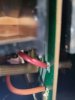
 
The transistors I mentioned that need checking are TR03, 04 & 05 of the F-2511 Protection PCB - a large square board with 2 relays on it. I am sorry I can't help with removal of this board or even how to get access to measure the 25V supply (measure across C02 on that board). This might not be needed, as thinking about it, RL02 runs of the same supply as RL01 and is energising OK.

The pictures of the thermistors are not very convincing, as you can't see if the fragile wires are OK, thus disconnecting them and measuring their resistance would be the simplest way to verify this. Knowing where the F-2511 board is and how easy it is to access is the key to this.

Don't try to remove those Output assemblies (pictures with yellow rings) unless you really have to.
 
Alright the F-2511 is very accessible, don't I need to remove it and remove the transistors to properly test them?

Also if you want me to test the thermistors I have no choice to remove
 
Alright the F-2511 is very accessible, don't I need to remove it and remove the transistors to properly test them?
Not necessarily, I am afraid you do need to remove the transistors to test them, you should not need to completely remove the board however, just remove the mounting screws and loosen any wiring just enough so you can remove them. If you don't have a transistor tester - look up "the six way test" for testing transistors with a multimeter.
Also if you want me to test the thermistors I have no choice to remove
No, that's not right - you can disconnect the wiring that connects them to the protection board at the protection board end.
the heat sinks that I have circled where I woyld need to desolder?
No! - you do not need to remove them. - see the above instruction.
 
You are right I can disconect the boards at the bottom but the top part will need desoldering I do beleive (see picture)?

Allright so if I get this correct I should loosen up the F-2511 enough to remove these transistors and test them? After this, would be pulling out the heat sinks and testing the thermistors? What specs Am I looking for from these thermistors?
 

Attachments

  • 20190811_154055.jpg
    20190811_154055.jpg
    56.6 KB · Views: 23
This is as far as it goes with me I am afraid, you need to learn a lot more about electronics before you attempt to repair an amplifier like this. Maybe I should have told you to take it to a tech at the outset, as I have better things to do with my time than laboriously type you out a book of instructions, that isn't how this site works.

I encourage you to use the search facility of this site, type 'PTH487A' into the search box - you will find a wealth of information this way.

Good luck.
 
Back
Top Bottom