TupolevFan
Super Member
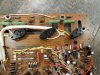
Good day everyone. A week ago I was passing by the yard sale and saw a dusty and a bit beaten up Sansui AU - 217. Owner asked 15 USD and I could not resist and picked it up. Came home powered the unit up and to my surprize relay clicked. I measured DC offset and one channel was almost perfect 3.2mV and the other was 135mV and jumping a bit around. I turned it off and disassembled. Made a list of Parts and caps for replacement + relay. Order arrived last Friday. I removed all more or less large caps from the main board and gave it a isopropil bath and some soap water with brash and then hair dried it  . The component side came out pretty clean but from the "solder" side there were some white traces from the isopropyl alcohol. Not sure what to use to remove them.
I started to replace the components(capps and resistors) and it was going OK until i lifted a trace and "string" of curses went out of my mouth.))) Then it happened couple of more times until i realized what is going on. I usually use a stainless steel needle to clean the whole from the solder (briefly hitting it up and sticking the needle in and pulling it out). The issue was that this time my needle was not stainless steel and the solder was sticking to it a bit better than i expected. So i was a bit upset with myself since reinforcing the trace does not look as nice as if I did not have to do it and extra operation wastes time.
I found all 220 Ohm(R39,R41, R40, R42) resistors out of spec the measurements were all over from 270 to 380 Ohm. Replaced them with 1/2 W 220 1% metal films. Also in a channel where DC offset 135mV i found that R35 was out of specs(82 Ohm was measuring 400+ Ohm). In the beginning I thought that high DC offset was most likely because of faulty differential pair 2SA798 and now after finding this resistor almost 5 times of it's value i am not so sure. Because the negative rail would be affected. I replaced all four 82 Ohms resistors. Plan to replace all small transistors with their ON Semmi equivalents. Not sure if i have to touch 2SA798 or do you guys suggest to replace it anyway? Output stage will be original as it seems like original are in good shape. replace dual diodes VD1212 with the pair of 1N4148 (if i remember the part# correctly). I almost completed to recap main board. Just was not happy with myself about lifted/damaged traces. There are R43,R44,R45,R46 6.8 Ohm resistors (they masure OK) should I replace those as well as they looked like those 220 Ohm resistors. If you could think about any other failure prone component in this amp please let me know.
Will Post some pics later
. The component side came out pretty clean but from the "solder" side there were some white traces from the isopropyl alcohol. Not sure what to use to remove them.I started to replace the components(capps and resistors) and it was going OK until i lifted a trace and "string" of curses went out of my mouth.
))) Then it happened couple of more times until i realized what is going on. I usually use a stainless steel needle to clean the whole from the solder (briefly hitting it up and sticking the needle in and pulling it out). The issue was that this time my needle was not stainless steel and the solder was sticking to it a bit better than i expected. So i was a bit upset with myself since reinforcing the trace does not look as nice as if I did not have to do it and extra operation wastes time.I found all 220 Ohm(R39,R41, R40, R42) resistors out of spec the measurements were all over from 270 to 380 Ohm. Replaced them with 1/2 W 220 1% metal films. Also in a channel where DC offset 135mV i found that R35 was out of specs(82 Ohm was measuring 400+ Ohm). In the beginning I thought that high DC offset was most likely because of faulty differential pair 2SA798 and now after finding this resistor almost 5 times of it's value i am not so sure. Because the negative rail would be affected. I replaced all four 82 Ohms resistors. Plan to replace all small transistors with their ON Semmi equivalents. Not sure if i have to touch 2SA798 or do you guys suggest to replace it anyway? Output stage will be original as it seems like original are in good shape. replace dual diodes VD1212 with the pair of 1N4148 (if i remember the part# correctly). I almost completed to recap main board. Just was not happy with myself about lifted/damaged traces. There are R43,R44,R45,R46 6.8 Ohm resistors (they masure OK) should I replace those as well as they looked like those 220 Ohm resistors. If you could think about any other failure prone component in this amp please let me know.
Will Post some pics later
Last edited: