• The move to the new server is done. There are some software and database maintenance updates in process. This has us passing the hat around to help out. We appreciate any donations. Seriously, even a dollar helps. The payment page may be found here - https://www.audiokarma.org/support.html

Sansui AU-517 humming

I'm sorry that you are still having problems, I just finished a restoration on my first AU-517 ( and my first restoration in general) so I don't have the experience to help you. Having said that have you tried swapping the wiring between F-2721 and F-2722, easy to do and you don't have to remove any parts. Disconnect the right channel and connect it's cables to the left channel see it you still have a hum running one channel, at least you can rule out the driver boards from your fault finding.
Do I also have switch the cables from the sockets? I did not do that when I performed this test when I started the hunt.

Today I put a few resistors in that were backordered and I will test again tomorrow.
 
Do I also have switch the cables from the sockets? I did not do that when I performed this test when I started the hunt.

P1020732.JPG

Simply remove all 7 connectors from the right driver board (your hum side) and replace then with the connectors from the left. You can then see if the hum is still present (you can test individually or both sides at the same time) . At least you will be able to rule out the driver boards as the source of the hum and narrow your search.
 
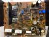
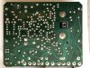
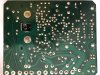
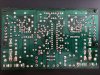
I am guessing that you took photos of the boards both before and after. Try uploading some here (after pics) including the solder side of the boards you have worked on. We have some superhuman techs in AK who may spot something us mortals can easily miss.
 
I am guessing that you took photos of the boards both before and after. Try uploading some here (after pics) including the solder side of the boards you have worked on. We have some superhuman techs in AK who may spot something us mortals can easily miss.
I finished checking the driver boards. This is the outcome: Left channel board with its own cables: clean and crisp sound Dim Bulb just a little glowing. Right channel board with its own cables crisp sound but buzzing.
Both channels: crisp but buzzing.
Now left channel board with right channel cables: crisp sound but buzzing
Right channel with left channel cables everything ok. This rules out a faulty driver board iI think. But iI tried another thing. I connected the right channel cables on the left board but left the white connector from left in its original place. No buzzing!
If I drive the right bord with the left cables and the right white connector: lots of buzzing. The connector goes to the backpanel F-2670 where I renewed the electrolytic caps (maybe polyprop had been the better choice) anyways the buz/hum originates from here. So I took the pre/main connector switch apart and cleaned it. I also put two old caps back. But now I have no sound at all.
I’ m still not fit for a job at Scotland Yard I guess. I will sent some before/ after pics later.
Thanks for being patient with an newby.
Hans
 
Last edited:
Hi fellow hum hunters,
So far so good, I managed to get the music back, so one worrie less.
But the hum still exist. It is only in the right channel, so I'm still checking wires and cables with my multimeter, starting from a grounding point on the chassis to the components boards.If I measure zere ohms I call it checked OK.
What I found until now were a few half broken or dried out connections that I reflowed.
Still nothing, I'l keep you all posted. In the mean time, if you think of something new to try, or if you find my approach inefficient, please tell me.

Hans
 
An update on the humming bird.
I found good ground to my boards but measured a strange difference on the cables that run from the PS to the tone control board: Red and Blue +12.8 and -14.8 Volts and Yellow and Gray +29.9 and -30.1 Volts. The specs say + and - 31V. Since they originate from the same places on th PS this problem is also replicated to the equalizer.
So the right channel to tone control is not getting enough juice.
Is this making any sense? I measured from the connector to ground. Could this be responsible for the humming?
I took out the powersupply to check every component. Measured all the diodes and only found D608 with a Vdrop of 275 in both directions (measured in circuit) i desolderd it and it maesured 575 in one direction and was blocked in the reverse direction, which is ok I think.
I,m lost I think.

Hans
 
I wish that I had an answer for you. There must be someone here who has an idea or two to help. Maybe I used up all the goodwill on 517's for now in my multi-million post restoration thread?
 
I walked through all the suggestions made by the AK members but I did not find something wrong. I think I know to little to tackle this problem on my own. Since sound was pretty OK when I started and still good when I was done recapping I think most of the boards are OK. So I checked every component on the PS and found that 13 resistors were out of spec, from which R603, R604, R607, R608 R611 and R613 (10-30% off)
Also the rectifiers have black feet, as if they have been very hot. I also found an old repair on the backside, where I found a solder pad lifted and bypassed. I remember there was an issue with it and my father had it repaired under warranty a very long time ago.
Questions I have are:
- is that repair ok, the way it is done?
- should I proceed with a complete overhaul of resistors and rectifiers, and relay?
IMG_6227.JPG IMG_6228.JPG
Thanks in advance
 

Attachments

  • image.jpeg
    image.jpeg
    132.5 KB · Views: 26
  • IMG_6227.JPG
    IMG_6227.JPG
    132.5 KB · Views: 25
  • IMG_6228.JPG
    IMG_6228.JPG
    148.1 KB · Views: 25
  • IMG_6227.JPG
    IMG_6227.JPG
    132.5 KB · Views: 25
- is that repair ok, the way it is done?
- should I proceed with a complete overhaul of resistors and rectifiers, and relay?

A jumper wire is a common repair and should be fine. If the lifted trace is still in one piece I tend to glue them back (and clamp or put pressure on overnight) with high heat epoxy for circuit boards. I kind of like it to look like it was never damaged in the first place. But who will ever see it anyway?

I would replace any component that is out of spec. The relay is worth replacing as part of a restoration anyway.

Did you replace D604? I think it is suggested on a restoration. D604 is a VD1212 (dual diode) can be replaced with a pair of 1N4148 diodes (in series) I think that this is the same as on the 517. Anyone please correct me if I am wrong.

I'm not saying that it is a problem but they are normally replaced, there are also several other VD1212's in your amp.

This pic is from my 515 and my diode's in series.
P1020788.JPG P1020957.JPG
 
So I checked every component on the PS and found that 13 resistors were out of spec, from which R603, R604, R607, R608 R611 and R613 (10-30% off)
You know you can't reliably test resistors 'in-circuit' ? - you have to lift one end of each so you measure only the resistor and not any surrounding components.

Definitely replace the relay - as it is the original. For the moment, only replace parts that could be directly responsible for the problem you currently have. ;)
 
You know you can't reliably test resistors 'in-circuit' ? - you have to lift one end of each so you measure only the resistor and not any surrounding components.

Definitely replace the relay - as it is the original. For the moment, only replace parts that could be directly responsible for the problem you currently have. ;)

What he said. He knows a thing or two.

Be very weary of anything I say without a second opinion.
 
You've been very helpful, here and in other threads, with excellent and encouraging help. ;)

Thank you for your kind words. Everyone, you included were so helpful to me on my first attempt at restoring my AU-517.
I feel in my inexperience here though that I took my eye off the ball so to speak as indeed fixing the existing issue with the hum should come before any further upgrades.
 
Thank you for your kind words. Everyone, you included were so helpful to me on my first attempt at restoring my AU-517.
I feel in my inexperience here though that I took my eye off the ball so to speak as indeed fixing the existing issue with the hum should come before any further upgrades.
Thanks Hyperion and Alex. I will check every component again…. A lot to learn!
 
You know you can't reliably test resistors 'in-circuit' ? - you have to lift one end of each so you measure only the resistor and not any surrounding components.

Definitely replace the relay - as it is the original. For the moment, only replace parts that could be directly responsible for the problem you currently have. ;)
Hi Hyperion,
I retested the resistors with one leg lifted. Some tested the same and the extreme differences were gone. But still a few out of spec, but not by much.
Tested all diodes. Forward Vdrop is fluctuating between 525 and 575 on the 30D2’s. I have no idea if that is normal and/or ok.
I ordered some replacement resistors, new zenders and an Omron relay. (Mouser)
I,ll keep you all posted.
 
Checking transistors I found differences between the left and right channel D438E (NPN) in left channel has hFE 136 and in the right channel channel 59!
The B560E's (PNP) had hFE 130 and 118. And the six C945A (NPN) had 322, 339,347, 354, but two of them had 54 and 97. This does not look right in symmetric channels does it? And KSA733C measured hFE 287
Do I need to replace all the transistors?
Are they good?
D438E with KSC2316YTA
B560 with KSA916YTA
C945E with KSC945CYBU
SA733C with KSA733CGBU
Is that OK or are there more modern parts (Mouser marked some as obsolete, EOL)
 
An update of my work on the humming Sansui AU-517:
- totally renewed my powersupply/speaker protector.-
- new transistors
- new rectifiers
- new zeners.
This board is working good, coming out of protection and producing +35,9 and -35,9 on the right channel and +36,0 and - 36,0 on the left channel. with no board attached. DBT stays off
This is 5 V above spec. Is that OK?
Tried again with everything hooked up. Left is playing very clean and fine. As soon as I connect Right driver amp: very loud buzz/hum not related to volume. And DBT ligt up moderate.
I am clueless. So I started to search and measure systematically (Should have done that much earlier. I found out that everything stays ok until I hook up the right channel powersupply to the equalizer amp. The leads not attached measure 35,9 (+ and -) and when attached the voltage drops to +14,3 on 24 and -15,4 on 28. When I measure the left side everything stays ok on 36 Volts.
Can someone please help me crack this problem?
 
...And DBT ligt up moderate...I found out that everything stays ok until I hook up the right channel powersupply to the equalizer amp. The leads not attached measure 35,9 (+ and -) and when attached the voltage drops to +14,3 on 24 and -15,4 on 28. When I measure the left side everything stays ok on 36 Volts...

The DBT lighting up and the voltage drop indicates that is short in the right equalizer circuit. Can you post a picture of the F-2723 board?
 
Back
Top Bottom