• The move to the new server is done. There are some software and database maintenance updates in process. This has us passing the hat around to help out. We appreciate any donations. Seriously, even a dollar helps. The payment page may be found here - https://www.audiokarma.org/support.html

Sansui AU-719 possible relay fault?

Ok forget about what i said regarding the fuse as i thought you were talking about primary fuse but obviously you spoke about secondary fuses (F01-F04).
As i understand you rebuilt the unit. What is installed instead of C601(is it the same value or you upped the value) ? What confuses me is how long those light emitting diodes (input selector and power indicator) stay lit after turning the unit off. Even multivibrator works a while after relay disengages. that tells me that the C601 and it's circuits are still energized. Question is Why. In normally working circuit main filter caps would have NO effect what so ever on this circuit as bridge rectifier would block them (if i could say so). I remember recently Ray Gianelli had a case of leaky rectifier diode and it was not blowing fuses. Just wonder if something like this is here but this would be strange as it is shunted by transformer windings unless transformer would act as a giant choke in this transient process. Well I would check C601 and then (i am not sure if you could do such an experiment) I would disconnect points 9 and 11 from the power supply (yes leaving C702, and C701 uncharged) and see if it does it again. Also as a safety disconnect corresponding driver board. This would clear any doubts if main filter caps have anything to do with it. If amp stops doing that and turns off immediately then i would suspect unconventional failure of D01,D03 bridge rectifier failure.
Nearly every capacitor is a like for like swap with modern Panasonic of Nichicon replacements, I did them one at a time to avoid any confusion too, it worked perfectly for years until recently when this protection problem started out of nowhere. None of the capacitors looks to be damaged so I'm not sure that could be the cause, also to be honest I'm a bit lost at troubleshooting that doesn't involve soldering in replacement parts haha, I might try replacing these transistors then see how that goes.

Great thanks for that Lee, I'm pretty sure these weren't available in 2013 when I started working on this.
 
Nearly every capacitor is a like for like swap with modern Panasonic of Nichicon replacements, I did them one at a time to avoid any confusion too, it worked perfectly for years until recently when this protection problem started out of nowhere. None of the capacitors looks to be damaged so I'm not sure that could be the cause, also to be honest I'm a bit lost at troubleshooting that doesn't involve soldering in replacement parts haha, I might try replacing these transistors then see how that goes.

OK.
Do the following :

On Power Supply board find points which are marked 09 and point 11. Wires will be connected to those points ( I think it will be red and blue OR it will be yellow and grey one of those pairs) Disconnect them from the board (you will need to unsolder them and note which connected to which point). Those are the wires which are connected to the main (big) filter caps. This would disconnect main filter caps from "equation". Turn the amp on and then turn it off in couple of seconds and see if this changes anything. If it does then i would think of replacing D01 D03. Problem is that I do not know anything that can be used as 1 to 1 replacement for those. May be this https://www.ebay.com/itm/291302286971?epid=1736748342&hash=item43d2f8267b:g:Hm0AAOSwaNBUbmaH. but i do not know how legit this is(i mean if those are not fake). Also you would need 2 parts S5151 and S5151R. Or you would need to be creative with regular diodes. BUT first test it as i say. Do not connect any speakers just unsolder those wires from 2 points and do a turn on turn off test.
 
Last edited:
You might need to get discrete rectifier diodes as replacements for the S5151 & S5151R, as far as I know those rectifiers are very robust and seldom fail.

Interesting fault, I'd like to know what fixes it, it would be disappointing if the fault was shotgunned and then went away without us discovering the root cause. ;)
 
Last edited:
You might need to get discrete rectifier diodes as replacements for the S5151 & S5151R, as far as I know those rectifiers are very robust and seldom fail.

Interesting fault, I'd like to know what fixes it, it would be disappointing if the fault was shotgunned and then went away without us discovering the root cause. ;)
John, my reasoning for rectifier is simple. If C601 was replaced 1 to 1 then there is no way it would sustain those circuits (relay and input selector indicators) to be energized for so long. So far the only thing I could think of are main Filter caps somehow feed them and the only way to do this is via faulty rectifier. But what derails my theory is that transformer secondary windings are shunting them. However lets not to forget that when you turn off the switch it initiates a "Turn off" transient process and it might be that transformer acts as a giant choke in this process. By the way if i am correct in this theory it is not very healthy for transformer as well.
 
Last edited:
So far the only thing I could think of are main Filter caps somehow feed them and the only way to do this is via faulty rectifier.
I think you are almost certainly right, I had a long think about this and came to the same conclusion, the effect is as if C601 on the protection board somehow acquires a large boost in capacitance, so your theory makes a lot of sense. ;)
 
OK.
Do the following :

On Power Supply board find points which are marked 09 and point 11. Wires will be connected to those points ( I think it will be red and blue OR it will be yellow and grey one of those pairs) Disconnect them from the board (you will need to unsolder them and note which connected to which point). Those are the wires which are connected to the main (big) filter caps. This would disconnect main filter caps from "equation". Turn the amp on and then turn it off in couple of seconds and see if this changes anything. If it does then i would think of replacing D01 D03. Problem is that I do not know anything that can be used as 1 to 1 replacement for those. May be this https://www.ebay.com/itm/291302286971?epid=1736748342&hash=item43d2f8267b:g:Hm0AAOSwaNBUbmaH. but i do not know how legit this is(i mean if those are not fake). Also you would need 2 parts S5151 and S5151R. Or you would need to be creative with regular diodes. BUT first test it as i say. Do not connect any speakers just unsolder those wires from 2 points and do a turn on turn off test.

Hey everyone sorry for the delay! I went away for work for the last few weeks.

So here's a bit more information that may help, I just took the top and bottom covers off my AU719 to try what TupolevFan had suggested and I noticed that a fuse had blown.

It was a 250V 7A fuse, (Here in Australia we use 240V power) I replaced it with a fuse of the exact same type, switched the amp on and the new fuse instantly blew too, strangely enough the amplifier continued to power on as normal and still has the same issue when powering off.

Still think I should try desoldering the yellow and grey wires at 09 and 11? Also should I also desolder the red and blue wires from the other two capacitors as well?

I should also mention all the capacitors are the same spec EXCEPT for the big four filter capacitors which have been upgraded to Gold Tune 15000uF 63V caps.

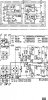
k3vHSWQ.jpg


kOFhTgE.jpg
 
blowing fuse is indication of short and possibly it is short in rectifier. blown fuse might be explanation why your caps are feeding the protection circuitry and not being shunted by transformer secondaries.

Second issue if memory serves me right is rating of your main filter caps. I remember that in my AU - 719 caps were rated at least 71V ( but i guess that there were variations for 63 V ??). May b e this is the main issue?
 
blowing fuse is indication of short and possibly it is short in rectifier. blown fuse might be explanation why your caps are feeding the protection circuitry and not being shunted by transformer secondaries.

Second issue if memory serves me right is rating of your main filter caps. I remember that in my AU - 719 caps were rated at least 71V ( but i guess that there were variations for 63 V ??). May b e this is the main issue?
The original filter caps were 6800uf 63V (I still have them) but they were replaced back in 2013 and haven't caused any issues in the last 9 years of daily use.
Also just to double check for troubleshooting do you still think I should try desoldering the yellow and grey wires at 09 and 11? Also should I also desolder the red and blue wires from the other two capacitors as well?
Cheers
 
Interesting as the Service manual calls for 10000uF. I assume that fuse you are talking about is F01 or F03. Now it is most likely that there is a short in rectifier D01 or D03.
I also want you to check voltage on ALL filter caps to see if it is not more that or at 63 Volts to make sure those caps are not constantly operating at surge voltages.

So this is the plan:
1. measure voltages and report back.
2. You will probably need to disconnect power supply board and test the rectifiers. put your multimeter in diode testing mode and test those D01, D03 ( each of those has 2!! diodes and each needs to be tested so in total you will perform 4 measurements). See if you can find the shorted one.
 
From the F-3101 board layout in the SM, it is the F01 fuse that blows on start-up. This fuse is also connected to the D601 and D602 rectifiers in the protection board; check these components for failure.
 
+1 what Lee said. I forgot about those. However i still think it is main filters rectifier as the way it acts suggests it.. The reason why it works after fuse blows is because it transforms it from dual half period rectifier into single half period rectifier and main caps will still be charged. However if it were D601 D602 failure and main rectifier was intact then main filter caps would not be able to feed protection circuit but it is obviously happening here.
 
Last edited:
This is really strange then.

The original filter caps were 6800uf 63V (

Not that I think it has anything to do with the current problem.

May be disconnecting the left channel transformer and see if the behaviour persists. ( Edit: I see left channel provides power to the protection so forget that.)
By the way, is this the multivoltage model (selector in picture) or CSA, or special modified version for Australia.
 
Last edited:
The difference in rail voltage is due to the lower AC secondary voltage, 41V as compared to 44V for the higher voltage models.

A quick check of the resulting DC voltage will tell you if that voltage was too high for the installed capacitors, I am pretty sure they are OK. (providing the AC mains voltage adjustment was set correctly).
 
Thanks for the input guys, I'll do these tests later today.
Just a few more notes, this amplifier was imported from the US to Australia in 2012, I immediately moved the jumper to 240V power where it has remained since, the original four 6800uF 63V capacitors were replaced with 15,000uF 63V capacitors as a recommended upgrade while the rest of the capacitors were replaced with like for like in 2013, it has been used daily since without issue other than a transistor that intermittently failed which has since been replaced.
It is a US domestic model with a 120V sticker on the side and a US power cable that has since been recabled.
Rectifiers are a bit of a mystery to me as my knowledge here is quite limited, I do have a good quality multimeter on me and am keen to test what I can if you let me know what I should be doing. Thanks again for all the advice.
 
Yes this is strange. And it's not like a small difference. And how can the multivoltage have the 41 v secundary's.
But like Hyperion said , easy measurement.
Would not surprise me if that capacitors were working in surge voltage level all there live.
 
So I did some tests and have some info share, it seems to me like one of the bridge rectifier diodes may be in fact be dead.

I took photos of every measurement just to be sure I'm measuring correctly so sorry for the image dump.

Both initially measured at 0V but after a while D01 started measuring correctly as if it became unstuck or something, D03 continues to measure at 0V however.


D01/D03
4moqGdL.jpg


YtZXDk6.jpg


This is how I've been measuring them.
kDRhnIh.jpg


All the rest seemed to measure around 0.489V


D06/D08
wFFEOkL.jpg

NtPW8Wh.jpg


D02/D04
UmBqnDN.jpg

k2PdUUA.jpg


D05/D07
X0vRzKb.jpg
RhmJNlL.jpg


Also D601 and D602 both measured at 0.462V

t6PhmPk.jpg


Also apologies but I seem to have misremembered two details, this amp has a 220V sticker and originally came with four 63V 12000uF capacitors, I must have confused this with the two I had lying around from my 8080 recap. Sorry about that. Here's an old pic before they were replaced.

DuEwclW.jpg


Before:
tvWMWur.jpg


After:
7XVOWKB.jpg
 
Back
Top Bottom