• The move to the new server is done. There are some software and database maintenance updates in process. This has us passing the hat around to help out. We appreciate any donations. Seriously, even a dollar helps. The payment page may be found here - https://www.audiokarma.org/support.html

Sansui Au-888 driving me crazy! Ideas?

Chriswashere

Active Member
Hey all, it has been a while since I posted. As per my usual disclosure I do this as a hobby and have been messing around for maybe 10ish years, but my lingo and understanding of some things is not the best so please stick with me.

Anyways, I have had this Sansui au-888 for about 5 years now give or take, and it has an issue I haven't been able to solve. Every blue moon this unit would suddenly violently crackle, sounding like normal crackling and then developing to thunder. I'd shoot up and power it down, first turning off the speakers since the noise would keep going until the amp ran out of juice. Doing research I found out that Sansui has a transistor problem with the CDC8002 and CDC9002 transistors known as "flying saucers" or "soup cans". No big deal! I went through both amp boards and the preamp (I believe, but it has been a while). And swapped out every soup can I saw. I did mess this up and there is a thread floating around about this, but that is not important as I sorted that.

Replacing these transistors seemed to do the trick, but apparently not. A few months ago the unit did this again, and blew fuse F003 as is tradition, so I set it in my dads stereo cabinet and moved on. After a few months of sitting we get to today. As usual I put in a new fuse but decided to put it on a variac set to 100V (should have done lower), and I turned it on. Immediately smoke poured out of the left channel so I shut it down.

I have pulled things apart and have found that F003, F005, and the left speaker fuse are all blown. On the driver board R825 was burned but all surrounding parts seemed to test fine, same with the 2sc111 transistors. Using a hickok transistor/diode tester I did poke every transistor and diode but found nothing that was a dead giveaway, but on the protection board there were 2 soup can transistors I missed (and now replaced), but the main concern is what caused this. Does anyone have any recommendations/ suggestions on what to do and what parts or areas to check that I may be overlooking? I was thinking of pulling the driver boards and output transistors and taking the voltage of each connector pin (not at full voltage though) and seeing whats what.

I also recapped f-1293 just because I had it out thinking the problem was there. Both transistors tested good in and out of circuit.

It's time to wrap this thing up so any help would be appreciated. This is one of those "keeper" units due to the long track history of messing up. I may be slow at responding due to other projects but will try my best.
 
Register to hide this ad
Better to wait for the sansui guru's who have first hand knowledge.
Smoke is a bad sign of further damage. F003, F005, L-spkr fuse and R825.

Need to track down root cause and all damaged parts before power up.

F003 is for positive rail left power amp unregulated power supply
F005 is for negative rail left power amp unregulated power supply
Check emitter resistors R853, 855, possibly smoked. Likewise R841, 843.
Diode check TR815, 817. Should really diode check all transistors in
problematic channel

R825, not sure how this fits in. Check TR805 and 807.

Blown speaker fuse suggests a speaker short.
Check resistance between fuse holder and chassis.

Looks like a speaker short.

Build a DBT for next power up.

Diode test transistors, test all 6 combinations.
 
Convenience on working on it.. for testing purposes, I'd disconnect output transistor leads. to test up to that point. The dbt will prevent those from being blown however for full power measurements don't connect the outputs up to that point. you won't be able to check bias without the outputs but better safe than sorry..
good idea to make sure soldering is good and retrace steps you've already done.
 
Check out the AU-999 restore threads in the Sansui forum - pretty sure there is a "crowbar" protect circuit in the AU-888, like there is in the 999, this may have been triggered. Its based around a triac - the wisdom may be to bypass this to do further work (especially now that it has been triggered) - certainly many of us with AU-999s have totally bypassed this circuit in our amps.

I would say your original issue was caused by a failing flying saucer (soup can) tranny or one of those old trimmer pots.
 
Better to wait for the sansui guru's who have first hand knowledge.
Smoke is a bad sign of further damage. F003, F005, L-spkr fuse and R825.

Need to track down root cause and all damaged parts before power up.

F003 is for positive rail left power amp unregulated power supply
F005 is for negative rail left power amp unregulated power supply
Check emitter resistors R853, 855, possibly smoked. Likewise R841, 843.
Diode check TR815, 817. Should really diode check all transistors in
problematic channel

R825, not sure how this fits in. Check TR805 and 807.

Blown speaker fuse suggests a speaker short.
Check resistance between fuse holder and chassis.

Looks like a speaker short.

Build a DBT for next power up.

Diode test transistors, test all 6 combinations.


Thanks! All suggested parts tested good, and there was no short between the fuse holder and the chassis. I am wondering if I had left the speaker selector switch on and somehow the leads of a speaker wire touched, but this isn't something that would be easy to happen. Oh well, what's done is done.

I am a bit confused by "diode test transistors" . Is there some sort of test procedure I am missing out on?

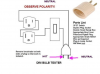
A DBT has been on the list for years. I actually have the "box" that works as the on/off for my shop light. I think the only issue is knowing which side of the plug is supposed to stay "hot".
 
Check out the AU-999 restore threads in the Sansui forum - pretty sure there is a "crowbar" protect circuit in the AU-888, like there is in the 999, this may have been triggered. Its based around a triac - the wisdom may be to bypass this to do further work (especially now that it has been triggered) - certainly many of us with AU-999s have totally bypassed this circuit in our amps.

Dang the way that circuit works is a nightmare and probably played a hand in what happened. Is there a guide about removing it as in how to bypass it and wire what to where? I see one guy posting his au999 restoration all over the internet and showing he removed the board, but there isn't much detail. Maybe I am missing something obvious and this is actually easy though. It looks as if I just remove wire A and wire B that are connected to the board and speaker fuses, with A being to the left channel and B being to the right. But it can't be that simple can it? I am trying to not have my lack of experience with fancier stuff cause more damage on this unit..
 
The crowbar disconnect may be as simple as removing two wires. That’s what Is done in an Eight with that goofy “protection” system.

I just rebuilt an amp in a Quadraflex 450R.
There are no service manuals.
I could see burned resistors and exploded transistors,

The outputs were removed and tested OK.
I replaced every burned resistor and exploded transistor.
I checked every diode and remaining resistor. One emitter resistor was open. It was replaced.
I removed and tested the driver transistors, they were replaced.
The bias diodes tested fine.
On power with the outputs removed, the base of the outputs showed high voltage on one output. All transistors had been replaced except the differential pair. The tested OK in circuit with an octopus on the o-scope.

I removed the differential pair and tested them and they were way out of balance. High Hfe on one, low on the other. I changed those and checked the output base voltage on the pads again with the outputs removed and things were good.

Reassembled, dim bulb OK. Full power and a spot check on bias by guessing test across the emitter resistors. Adjusted to match good side and she sings like an angel.

Moral of the story? Where there is smoke, a lot of things can be fried. There were 5-6 resistors toasted and every transistor except the outputs were bad.

Test all resistors, diodes and transistors but don’t trust the transistors that test good. Under full power, things are different than in the meter test.

Luck.
 
I think the only issue is knowing which side of the plug is supposed to stay "hot".
the diagram posted shows the large tang is Neutral the small tang is hot. Plugging in amps w/equal tangs won't matter but units with the offset will be correct.
 
Indeed, the crowbar circuit can be removed just by cutting or taking out the two short wires from it which go to the loudspeaker fuses. It is the marked A and B ones, here.
It comes in at about 8 Volts DC and it protects the speakers from being destroyed by DC out of the amp if an amp channel goes defective.
crowwires.jpg
 
the diagram posted shows the large tang is Neutral the small tang is hot. Plugging in amps w/equal tangs won't matter but units with the offset will be correct.

Which leg the bulb is on doesn't matter.
It's an AC circuit.
 
Thank you! I cut out that board but need to do proper testing. It passed the dim bulb test without exploding which is always a plus, though this was without the power transistors installed. Next is to variac it and then check voltages I guess, or should I be doing something else for safety? That method hasn't failed before but it could always be wrong.
 
Do voltage check on dim bulb.

Dim bulb controls current so voltage is correct.
Variac controls voltage but you get full current.

Use Variac on tube gear.
Use dim bulb on solid state gear.

If it passes dim bulb. You can use full line power and check the output connections for correct voltages. If the voltages at the connections is way off, you still have amp problems.
 
OK - if you replace the outputs and have an issue on dbt - then that will be a pointer that some outputs have blown. Could also mean runaway high bias - depending on what shape your existing trimmers are in
 
Do voltage check on dim bulb.

Dim bulb controls current so voltage is correct.
Variac controls voltage but you get full current.

Use Variac on tube gear.
Use dim bulb on solid state gear.

If it passes dim bulb. You can use full line power and check the output connections for correct voltages. If the voltages at the connections is way off, you still have amp problems.

This is really good info! I was always told to use the Variac on everything for years and to never bother with a DBT, being told they were "unprofessional". Not really sure why they would be. I also never knew if it passed the DBT it was ready for full voltage.
 
OK - if you replace the outputs and have an issue on dbt - then that will be a pointer that some outputs have blown. Could also mean runaway high bias - depending on what shape your existing trimmers are in

For me the outputs are what I was taught to check out first to get an idea of the damage. They tested fine but I will certainly look at those trim pots. They don't look super clean/ in good shape. Usually the Sansui units I get have the same nasty pots in them.
 
You should be running a 60w bulb for small units like that.

Are the outputs still removed?
 
Back
Top Bottom