• The move to the new server is done. There are some software and database maintenance updates in process. This has us passing the hat around to help out. We appreciate any donations. Seriously, even a dollar helps. The payment page may be found here - https://www.audiokarma.org/support.html

Sansui AU-919 Needs Love.

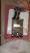
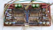
Have taken F-2835 and F-2834 out together from the parts unit. I kind of want to put it in the other 919 and test it but do not want to put it in and out multiple times (and stress the ribbon cables) so I guess I should recap it first. A job for tomorrow time permitting.
 

Attachments

  • 20250214_200114.jpg
    20250214_200114.jpg
    110.9 KB · Views: 16
  • 20250214_200110.jpg
    20250214_200110.jpg
    105.4 KB · Views: 16
Ok F-2835 is recapped just have to swap it for the damaged one. Wile I have F-2835 and F-2834 out of the amplifier is there any other board that should be addressed while the amp is partially disassembled, apart from maybe the pre/main switch? Am hoping not to have to disturb F-2835 and F-2834 again. But don't really want to recap multiple boards to simplify any possible fault finding if I screw up. Thoughts.......
 
Thoughts.....
I think you'll be wanting to consider the MC Head Amp Board (F-2833), and the Protection Board (F-2840), and really the Pre-Main Switch Board too. They are all rear panel related, and require manipulation of those ribbon cables, quite a lot easier with the rear panel connector board unscrewed. (That is, IF you haven't desoldered the ribbon cables at the F-2835 board end - which I have found is the easiest way to tackle this part of the restore). ;)
 
Thanks Hyperion that is exactly what I needed to know. Desoldering the ribbon cables (read quite a few of your posts over the last few years) is better but I still hesitate at doing more desoldering/resoldering than I have to, just a lack of experience on my part, if I keep grabbing up old Sansui's them maybe that will change.
 
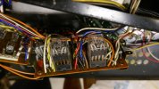
I have removed F-2835 and an ready to work on (F-2833), (F-2840), and the Pre-Main Switch.

On detailed inspection of the selector switch I believe I have identified the problem.

Take a look and see if you can also spot the small issue

55DC120E-2694-4E19-9EB7-1AB8D7211F68_1_201_a.jpeg
 
Last edited:
Oh Boy, it just might be repairable - with epoxy adhesive - IF - there is no other damage to the switch, if that isn't enough already. :rolleyes:

I'm willing to give it a go, wouldn't put money on a favorable result. But it is kind of my favorite type of repair. nothing to loose if it doesn't work and something to gain if it does.
 
Can you imagine how that happen ?
The person trying to remove the soldered switch from the PCB , thinking that is a
plug-in ….
It looks bad but it’s repeatable to my eyes.

Clue together with super glue the PCBs and solder-run over the traces 0.2mm copper wire and I think it will be better than new.
I’m interested to see how you going to tackle that , I like my self this kind of repairs !
 
Can you imagine how that happen ?
The person trying to remove the soldered switch from the PCB , thinking that is a
plug-in ….
It looks bad but it’s repeatable to my eyes.

Clue together with super glue the PCBs and solder-run over the traces 0.2mm copper wire and I think it will be better than new.
I’m interested to see how you going to tackle that , I like my self this kind of repairs !
It happened according to the seller some 30 years ago, it took a solid hit when moving the unit to the input selector knob which pushed the selector rod into the switch mechanism, from what I see this is exactly what happened. If no small parts are missing I will attempt a repair in the future. For now I have a spare board ready to pop in.
If I do attempt a repair I will be sure to post the results.
 
Ok so almost finished the protection board F-2840 just the relays, the Omron MY4-02 DC24 has four more legs than the originals my hazy memory tells me to cut them off so thats the plan. My question is how often do these relays go bad? These two look like new, I may leave them in as I don't mind replacing them in the future, if they are a generally unreliable part then replacing them now would make more sense.
 
if they are a generally unreliable part then replacing them now would make more sense.
Due to being caught out by one or two shiny looking speaker relays in the past - unless they pass my contact resistance test - the old ones get filed in the 'square filing cabinet' on the floor, and a new one, also tested in the same way gets installed. ;)

What is the test?
Relay removed and 24V DC PSU connected to the relay coil and all contacts checked for contact resistance of 0.3Ω or less, (usually 0.2Ω), and that has to be repeatable with multiple relay energisations. ;) Any deviation from that and the relay is out, I don't bother with 'cleaning' the relay contacts - that's usually a waste of time, especially with the cleaning methods I read on here from time to time. :rolleyes:
 
Last edited:
MC Head Amp Board, the Protection Board (F-2840), and the Pre-Main Switch Board are ready to put back in.
Left my favorite job for last, replacing the thermal paste on four transistors on the equalizer board F-2835. Who could not love the wonderful sticky mess I get myself into every Fracking time.
Which gets me thinking of the main output transistors. Of course the originals are coming out today for safe keeping until the unit is fully recapped and hopefully stable, temporary substitutes will be installed. I have seen on at least one other post that it may be possible to forgo the thermal compound and just use mica alone temporarily, bearing in mind that I will only be powering it up for literally seconds after completing each remaining board. If I have enough thermal pad material laying around I can cut that up to make temporary thermal insulators (better option in my opinion).
Planning on using one of the 2 methods above on the outputs unless I get some "Are you insane!" responses.
 
I would remove the outputs carefully so I leave the micas on the heat sink. Then I would put the temporary ones with out any new silicone or bothering to clean at that point .
When I finish with checking my things , I would instal the original outputs after cleaning the old silicone.
New mica and silicon .

I hope I understood your question correctly.
 
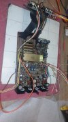
MC Head Amp Board, the Protection Board and the Pre-Main Switch Board are installed along with F2835 so hopefully have a working selector switch. Also swapped out the 10amp fuse for a 5amp one due to the change from 110v to 240v.
 

Attachments

  • P1040276.JPG
    P1040276.JPG
    99.7 KB · Views: 14
  • P1040271.JPG
    P1040271.JPG
    123.7 KB · Views: 14
  • P1040279.JPG
    P1040279.JPG
    89.1 KB · Views: 14
Oh forgot to mention. Powers up and comes out of protection.
Driver board then power supply boards next, may have to hunt around for nuts and bolts as I expect that I will be modifying F-2845 while I'm at it.
 
Back
Top Bottom