• The move to the new server is done. There are some software and database maintenance updates in process. This has us passing the hat around to help out. We appreciate any donations. Seriously, even a dollar helps. The payment page may be found here - https://www.audiokarma.org/support.html

Sansui AU-919 Restoration

Aud10file

AK Subscriber
Subscriber
A few months ago, @Vintagear pinged me, regarding an AU-919 on CL that looked amazing in the pictures. He knew I’d been looking for a good condition 919 for a long time. We immediately sped to the seller’s location. I drove and @Vintagear held on for dear life. LOL.

The seller was an older gentleman with quite a large collection. He was moving out-of-state and was selling off what he could before the move. He allowed me to quick test and also remove the cover to inspect the insides. I had to fight to keep my excitement down, and quickly purchased it, as it appeared to be a pristine and untouched specimen. It was in excellent cosmetic condition, had the original outputs, black flags galore, and it worked. This was a perfect candidate for full restoration.

It has sat in the “to do” section of my shop until, between customers, I could free up some time to work on it. My plan for this unit was to restore it to the original as-designed state without any value modifications, if I could help it. I’ve had a couple of weeks to focus on the 919 and have completed the bulk of the work. I figured I’d start documenting the work in a post now, before I start to forget the important details.

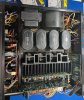
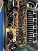
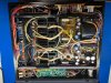
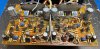
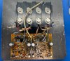
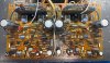
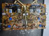
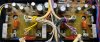
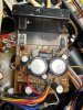
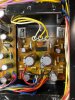
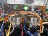
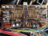
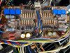
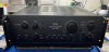
Here are some pics, before work began:
Front.jpg
topBeforeSheielded.jpg

TopBeforeUnshieldedcropped.jpg

MMandDriverCloseBefore.jpg

bottomBefore.jpg


First things first

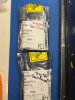
I took out the original NMC1012/NMA1012 output transistors and put in some sacrificial MJ21193G/MJ21194G transistors. This was done as insurance to protect the unobtanium outputs from any mishaps, while the restoration was completed.
sacrificial.jpg

originalOutputs.jpg


The real work begins next post….
 
Last edited:
Register to hide this ad
I love seeing how the better Tech's deal with the various issues presented by an amplifier like this. I'll be watching on the sidelines, but not to criticise, just for the entertainment value of seeing another one of these beauties restored to perfection. ;)
 
Awesome! Good idea to preserve the outputs from any mishaps.
I scour CL here in NJ, but never find anything worth looking at, how did I miss this???
 
The OP has already done an AU-X1, so an AU-919 should be a breeze for him ;)

I estimate there is roughly half the work doing an AU-919 compared to an AU-X1 - but of course it does depend a lot on the condition of each unit.
 
Yes, the AU-X1 is even more intimidating from a restoration perspective.
That's why I still did not get one from Japan.
By the way, with intimidating I was referring to the fact that this is a serious piece of audio amplification!
Recently see a video about a Yamaha S-xxxx amplifier costing up from € 3500.
They were heralding the "new" design, with short wires from transformer to rectifier to capacitors to output transistors. And the fact it had a separate regulated supply for the pre-amp boards. Hahaha, nothing new about that. Look at this AU-919. Seperate transformer and regulated powersupply for the pre amp boards, seperate powersupply for the MC-headamp board. Short wires through the whole main powersupply. Plus a ripple filter ( capacitor multiplier, but I like ripple filter better ) for the input and VA stages of the driver board.
Total of 7 powersupplies!
Amazing piece of engineering!
 
Awesome! Good idea to preserve the outputs from any mishaps.
I scour CL here in NJ, but never find anything worth looking at, how did I miss this???

You might have seen it and overlooked it like I almost did.

I think the listing was for "Hi-Fi Collection For Sale" or something like that, located in NY. There was a general picture of gear but the ad also had pictures of about 4 typed out pages of the items that were for sale. I almost didn't bother reading it but when I zoomed into the spreadsheets I saw an AU-919 listed about midway through one of the pages. I knew that @Aud10file was looking for one so even though the ad seemed like scam bait, I sent an email to the seller asking if the 919 on the list was still available and if so, what condition was it in. Seller replied that it was available and in perfect original condition, never repaired but that he was going on vacation and could not send pictures until the following Sunday when he returned. I was suspect but I figured let's see what happens next week and gave @Aud10file the info.

The following Sunday @Aud10file followed up with the seller, spoke with him on the phone and got a picture. The rest is history :D.
 
Last edited:
You might have seen it and overlooked it like I almost did.

I think the listing was for "Hi-Fi Collection For Sale" or something like that, located in NY. There was a general picture of gear but the ad also had pictures of about 4 typed out pages of the items that were for sale. I almost didn't bother reading it but when I zoomed into the spreadsheets I saw an AU-919 listed about midway through one of the pages. I knew that @Aud10file was looking for one so even though the ad seemed like scam bait, I sent an email to the seller asking if the 919 on the list was still available and if so, what condition was it in. Seller replied that it was available and in perfect original condition, never repaired but that he was going on vacation and could not send pictures until the following Sunday when he returned. I was suspect but I figured let's see what happens next week and gave @Aud10file the info.

The following Sunday @Aud10file followed up with the seller and spoke with him on the phone and got a picture. The rest is history :D.
I do recall seeing that one, but thought it was flaky.
There is the scammer guy with a lot of ads, $0.00 He's been around a while. Uses photos from others, and always a different location.
https://philadelphia.craigslist.org/ele/d/jenkintown-sansui-9090db-receiver/7491042913.html
 
Now that the unobtanium output transistors have been replaced with the sacrificials, I was able to conduct a proper pre-assessment of the amp:
  • Scratchy control potentiometers (i.e., balance, tone, and switches)
  • Volume pot was fine
  • Line level inputs satisfactory and functioning
  • Phono MM working acceptably
  • Phono MC sounds fine
  • All LEDs function
  • No apparent rework that could be discerned
  • Top cover has a few tiny scratches
  • Preamp/poweramp switch missing one screw and the clear plastic switch lock
  • Faceplate is flawless
  • Serial number lists the production date at April,1979.

Quick sound testing on the bench after DeOxit of the controls was quite good. Normally, I do some power testing before a restore, but there was no point in this case, since the original output transistors were in protective custody.

My general goals for this unit:
  • Keep the unit true to the original design
  • Make no component value modifications (higher max voltage for caps okay)
  • Use Nichicon throughout for the electrolytics
  • Use COG for the “black flags”
  • Employ sealed multiturn for trimmers
  • Replace zeners with 2% tolerance versions, if on hand
  • Replace any components that were damaged by Sansui glue

Time to dive in. The first board up was the Driver Amp Circuit board.

F-2839 – Driver Amp Circuit Board

The board in this 919 appears to be a different revision than others that I have seen here on AK. The differences are minor:
  • Main difference is that this one has an Ⓐ screen printed on the top right edge where other boards have a Ⓒ printed on them
  • C39, C40, C41, C42 are polystyrene on this board, not black flags
  • FET01 and FET02 are in a different package than others I have seen

There were no major issues during recap here, other than the disassembly which was a PITA. I cleaned the old thermal compound off the outputs and replaced the mica. However, I did not add new thermal compound since these were the sacrificials. I plan on adding new silicone compound when I install the original outputs. I did clean and renew the compound on the drivers.

Here are some before pictures:

DriverAmpDirtyBefore.jpg

DriveWithSacrificialBefore.jpg

DriverAmpTopViewBefore.jpg

Here’s an after picture:

DriverAmpAfter.jpg


F-2845 Power Supply Circuit Board for Power Amp Section

This one was straightforward. The only item that needs to be mentioned is the C11-C14 are listed in the service manual schematic as 100uF/63V; however, the actual value in this amp was 220uF/63V for these capacitors. There was also quite a bit of Sansui’s favorite glue holding the larger electrolytics down. It took a bit of cleaning to clear this up.

Before picture:

PowerSupplyF2845Before.jpg


After picture:

PwerSupplyAfterCropd.jpg


F2844 Power Supply for Pre-Amp Section

Note that the polarity for C07 and C08 are incorrectly printed on the board. (Good thing it’s an ingrained habit for me to note component positions, before removing them from the board.) This one was easy and quick. The transistors received new mica and thermal compound.

Before picture:

powersupForPreampBefore.jpg


After picture:

PowersuppfroPreampAfter.jpg


F-2838 Circuit Board Between Pre and Main amp

It was easier to remove the switch board on the 919 than it is on a 517/717.

Sorry, there’s no before and after picture. My excuse: It was late and I was very tired that night! Just imagine a 717 preamp/poweramp switch board.

Four more boards remain to be restored on this amp. To be continued…
 
Very smart to take out those outputs! I should have done that with mine when I restored it, luckily I had no problems and they survived the restore :)

Looking really good! No rust or paint damage internally, very nice. Can't wait to see more :beerchug:
 
Good looking work!
One thing I noticed when restoring my AU-D907 and what is evident here to is that on this amplifier the regulated power supply and ripple filter function without any excessive heat generation. Especially compared to the AU-X17 series but also to the following AU-D11/D9 series. I do think that is a big plus for this amplifier and the AU-819.
Outside of the "black flags" and the glue there is little to none to worry about ( and the outputs unobtainability).
Just sad that to keep the capacitance the same the capacitors get so small.
On the AU-D707 I used the Nichicon audio series (muse?) And some Silmic II.
I do think they are also relative low impedance and ESR. ( There delta Tangens is small, and leakage is about the same as the low ESR caps).
I mean Sansui used them ( Silmic) in the alpha series for powersupply and decoupling duty.
 
I suggest that you use Panasonic FR electrolytic caps in as many places that you can where polar electrolytics are needed. I have a high regard for them because ECHOWARS first choice was Panasonic FM and these are the Same ESR as FM. Just a wider selection in the FR. They also have the longest life and highest temp rating. Tougher and longer life is what you get.
And WIMA film caps in the places that you can.
This is just a starting suggestion.
Happy soldering!
 
Last edited:
I suggest that you use Panasonic FR electrolytic caps in as many places that you can where polar electrolytics are needed. I have a high regard for them because ECHOWARS first choice was Panasonic FM and these are the Same ESR as FM. Just a wider selection in the FR. They also have the longest life and highest temp rating. Tougher and longer life is what you get.
And WIMA film caps in the places that you can.
This is just a starting suggestion.
Happy soldering!
Panasonic is a great brand and I use these sometimes, however, I am partial to Nichicon and that is reflected in my parts inventory. One of the goals of this particular project was to stay true to the original design as much as possible. This meant not using films in place of electrolytics in this unit.
 
Wow! You are really making progress!
You must have done this before.
:):thumbsup:
PS. Please excuse my ignorance.
I tend to post before I have read enough (such as above). :rolleyes:
 
Last edited:
Progress made so far:

Four boards down, four to go. Despite the progress made so far, these remaining boards were more difficult to access for component replacement and required a greater investment of time.

F-2840 Protector Board

To access this board for component replacement, the rear panel needed to be loosened, so that the board could be removed from the panel. The board contained several zener diodes, several capacitors, and two relays. Both C3 and C4 were bipolar 220uF/6.3V and were replaced with 220uF/16V BP. C601 is listed as 100uF/50V on the schematic, but it was 47uF/50V on this board so this was the replacement value.

The relays tested strong during pre-assessment. Visual inspection showed the contacts to be clean with no oxidation or soot, so they were left in place. Normally, I would replace the relays on a restore, but since I intend to keep this amp, I can defer the relay replacement to a later time or when needed.


Before picture:

Here’s my top view, my before picture of the protector board was severely out-of-focus. My hope is that this one will satisfy.

protectorBoardBefore.jpg


After picture:

protectorBoardAfter.jpg


F-2833 MC Head Amp Board

This was the logical choice to tackle next, since the back panel was already loose. I should mention that I test all functions as each board is completed. Investing the small amount of extra work to test each board as it’s completed can be a real timesaver if you run into any issues while restoring.

I then replaced some of the polyester caps with new polypropelene. C03-C06 were replaced with Nichicon UFW series, as this was what I had on hand.

VR03-VR06 were 33KΩ on the board. I replaced this with 50KΩ multiturn, as this was also readily available in my inventory. VR01 and VR02 were 220Ω and were replaced with 200Ω multiturn.

The trimmers dialed in perfectly on post adjustment and testing.

Before picture:

MCboardBefore.jpg


After picture:

MCboardAfter.jpg


Just two boards left to do! Stay tuned...
 
Last edited:
Back
Top Bottom