• The move to the new server is done. There are some software and database maintenance updates in process. This has us passing the hat around to help out. We appreciate any donations. Seriously, even a dollar helps. The payment page may be found here - https://www.audiokarma.org/support.html

Sansui AU-9500 – Distortion in Right Channel (Need Advice)

Photoshark88

New Member
Hi everyone,
I’m working on a Sansui AU-9500 and could use some advice.

Background / What I’ve done so far:
  • I bought this amp with only one working channel.
  • On the right channel power amp board, I found:
    • Burned resistors
    • Two bad transistors
    • One shorted output transistor
  • I replaced all the caps on the power amp board and installed new output transistors.
  • Replaced all caps on the EQ board F-2029.
  • Replaced caps on the power supply board.
  • Replaced all caps on the tone control block F-2019 for the right channel only, also replaced 2sk30 transistors on j210.
  • Cleaned all pots and switches thoroughly.

Current status:

  • DC offset adjusts easily on both channels, no problem.
  • Bias adjustment through the resistor test points shows -0.1 mV or 0.0 mV on both channels.
  • Left channel sounds very good.
  • Right channel still has distortion and is about 30–40% quieter than the left.
  • I swapped the preamp boards: restored/prepped one works perfectly in the left channel, but the right channel still distorts.
  • Even if I connect a source directly to the preamp, the right channel still distorts, so the issue isn’t just in the front end.

Question:
Where should I go next with troubleshooting? Any common failure points or things I might have missed?
Thanks in advance!
 
Register to hide this ad
Indeed isolate the problem. For starters the pre out / power in could be swapped. This will tell you pre amp-eq section or driver-power amp section. Im willing to bet on a driver board problem (such as a signal transistor that passes signal but is leaky), but this is only a single possibility. Im sure you have one of the very hard to read schematics lol, keep us posted and best wishes.
 
Current status:

  • DC offset adjusts easily on both channels, no problem.
  • Bias adjustment through the resistor test points shows -0.1 mV or 0.0 mV on both channels.

Please explain how and where you are getting those bias readings? What test points? If it is on an output transistor emitter resistor it indicates you have no bias current.
With your methodology does the bias adjustment have any effect?
 
If you have (or can borrow) a sine wave signal generator and a 'scope, that will tell you for certain where the signal is getting corrupted.
Use an 8 ohm resistive load, not your speakers. (it's a safety thing, just in case you make an oops.)
Don't forget, you need to trace all the way to the output connectors.
The speaker selector switch, the output connectors, and most critically, the protection relay could be bad.
If the relay is original, it's a good idea to change that out now.
Given you have one working channel for comparison, this exercise shouldn't take long.
 
Please explain how and where you are getting those bias readings? What test points? If it is on an output transistor emitter resistor it indicates you have no bias current.
With your methodology does the bias adjustment have any effect?
I follow by this instruction from kevzep
Connected to the emitter resistor like on photos in the next reply below and I got -0.1 mV or 0.0 mV
 
I follow by this instruction from kevzep
Connected to the emitter resistor like on photos in the next reply below and I got -0.1 mV or 0.0 mV
That being the case it certainly seems to me that you have no bias in the right channel. Did you check the left channel to see what kind of reading you get there?

Nothing better than a working channel to compare to. :)
 
That being the case it certainly seems to me that you have no bias in the right channel. Did you check the left channel to see what kind of reading you get there?

Nothing better than a working channel to compare to. :)
Before starting to check the right channel, I started from the left channel that sounds good, and there I have 0mv.
 
Before starting to check the right channel, I started from the left channel that sounds good, and there I have 0mv.
Not sure what to tell you. No voltage drop across an emitter resistor indicates no current flow. Why TBD.

Did you check across any other emitter resistors, ideally they should all have the same voltage drop.
 
Not sure what to tell you. No voltage drop across an emitter resistor indicates no current flow. Why TBD.

Did you check across any other emitter resistors, ideally they should all have the same voltage drop.
tried on the 2 of 4 that i can touch, and its same. Im going to my friend this weekend that has oscilloscope, we will try to figrout where is the issue.
 
Hello everyone,

Just an update after the long weekend. I visited a friend who has an oscilloscope and a bit more electronics knowledge than me. He traced the voltage from ground to the body of the output transistors and found that the left channel was showing 45V, while the right channel was only 0.85V.

We started checking the wiring and discovered that one of the 7A FUSE had blown. It was located in a silicone tube underneath the amp. After replacing this fuse, the 45V came back as expected.

Next step: I still have distortion on the right channel. The sine wave on the oscilloscope wasn’t clean—there were some interferences. We decided the volume pot might be the culprit since cleaning didn’t help. I fully disassembled the pot and cleaned it thoroughly, but unfortunately the distortion remains.

I’ve ordered a new volume pot—it should arrive within the next 2 weeks (hopefully sooner). I’ll let you know the results once it’s installed.

On the positive side, I also finished recapping all the boards: power board, EQ board, power amp boards, and the tuner board.
 

Attachments

  • photo_5888917049701419603_y.jpg
    photo_5888917049701419603_y.jpg
    105.9 KB · Views: 8
Last edited:
Hoping you didn't get your new pot from ebay.

Most of those new pots listed are garbage for various reasons.

Use the scope to check the signal coming into each board, then going out to narrow your search.
Inject a 1khz signal in the Aux. jacks and follow it through until you discover the bad signal. Now you have a good idea where to concentrate as you search that board.
 
Last edited:
Hello everyone,

Just an update after the long weekend. I visited a friend who has an oscilloscope and a bit more electronics knowledge than me. He traced the voltage from ground to the body of the output transistors and found that the left channel was showing 45V, while the right channel was only 0.85V.

We started checking the wiring and discovered that one of the 7A resistors had blown. It was located in a silicone tube underneath the amp. After replacing this resistor, the 45V came back as expected.

Next step: I still have distortion on the right channel. The sine wave on the oscilloscope wasn’t clean—there were some interferences. We decided the volume pot might be the culprit since cleaning didn’t help. I fully disassembled the pot and cleaned it thoroughly, but unfortunately the distortion remains.

I’ve ordered a new volume pot—it should arrive within the next 2 weeks (hopefully sooner). I’ll let you know the results once it’s installed.

On the positive side, I also finished recapping all the boards: power board, EQ board, power amp boards, and the tuner board.
Some good advice from others. Did you scope the signal going into and coming out of the pot?

I think you talking about a 7A power rail fuse, not a resistor.
 
Hoping you didn't get your new pot from ebay.

Most of those new pots listed are garbage for various reasons.

Use the scope to check the signal coming into each board, then going out to narrow your search.
Inject a 1khz signal in the Aux. jacks and follow it through until you discover the bad signal. Now you have a good idea where to concentrate as you search that board.
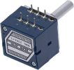
There are not many opportunities for volume pots, especially if you need a large-sized dual pot. I picked up an ALPS RK27 from AliExpress based on the feedback and reviews. Any other pots are small, like guitar pots or ones for compact units.
1756838768961.png
 
Hoping you didn't get your new pot from ebay.

Most of those new pots listed are garbage for various reasons.

Use the scope to check the signal coming into each board, then going out to narrow your search.
Inject a 1khz signal in the Aux. jacks and follow it through until you discover the bad signal. Now you have a good idea where to concentrate as you search that board.
As I said, based on the oscilloscope’s sinusoid, it’s a bad volume pot.
 
Back
Top Bottom