• The move to the new server is done. There are some software and database maintenance updates in process. This has us passing the hat around to help out. We appreciate any donations. Seriously, even a dollar helps. The payment page may be found here - https://www.audiokarma.org/support.html

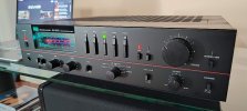
Sansui AU-D55X Repair and Restoration

p4spooky

Active Member
Acquired a non working AU-D55X for the price of a lunch at McDonalds :cool:

Not a lot of talk here on this model, found couple of useful threads HERE and HERE (incomplete thread). Although this was released around 1983, I was intrigued by the "Super Feed Forward" circuit and its impact on the distortion and possibly sound. Also like the form factor, similar to AU 317 (which have restored and love the sound). Wanted to get this one going to see how this compares to the AU 317 in particular.

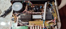
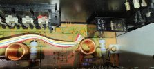
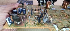
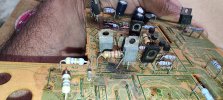
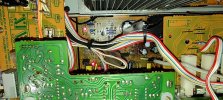
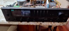
It was clearly sold as a non working unit "No power". Opened it up and did a through visual inspection. Missing main fuse which is never a good sign. Luckily this model does have a removable bottom cover. Three output transistors blown, NPN on the right channel survived.. Started with my meter and the service manual and checked all transistors on the left channel along with diodes and fusible resistors. Interestingly all fusible resistors measured perfect although I found catastrophic damage to the transistors on the left channel. Right channel appeared OK except for a shorted PNP output.
IMG_20260813_185856142_HDR.jpg

Showing left channel damage. Used the right channel from SM as left channel is busy with values and audio path marked by Sansui.
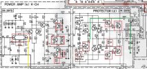
AU-D55X - Left Channel damage.jpg

I did not catch the FET failure on the left channel during initial check. If you notice KQ1 and KQ2 survived along with its current source KQ3 so I assumed the FET should be OK. Read on as I found out later that the FET was indeed damaged.

Initial observations and decision to scrap or move forward

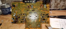
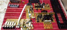
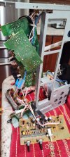
1. The amplifier circuit is split across two boards F3975 and F3976
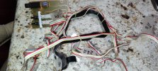
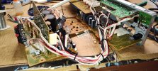
2. The bias transistor KQ8 is installed on F3976 with ribbon cables going everywhere
3. F3975 is partially blocked by F3982 (Input selector and Muting) board
4. Non standard relay AP2U (24V)
5. Power supply/Protection and Multivibrator circuits F3989 mounted vertically on F3976
6. Regulated power supply on F3976 (+-20/+-22V) with positive rail running HOT
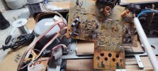
7. The best way to work on this was a complete disassembly IMO.
8. Decided to do a FULL restoration while I had all the boards out provided the main transformer was not shorted.
IMG_20260816_100724540.jpg
 

Attachments

  • IMG_20260813_185903647.jpg
    IMG_20260813_185903647.jpg
    131 KB · Views: 15
  • IMG_20260813_190029256.jpg
    IMG_20260813_190029256.jpg
    116.3 KB · Views: 13
  • IMG_20260814_175750626.jpg
    IMG_20260814_175750626.jpg
    158.1 KB · Views: 9
  • IMG_20260814_183453086.jpg
    IMG_20260814_183453086.jpg
    110.1 KB · Views: 10
  • IMG_20260814_183707109.jpg
    IMG_20260814_183707109.jpg
    138 KB · Views: 12
  • IMG_20260814_183719241.jpg
    IMG_20260814_183719241.jpg
    131.7 KB · Views: 13
  • IMG_20260814_185321888.jpg
    IMG_20260814_185321888.jpg
    134.4 KB · Views: 12
Register to hide this ad
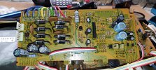
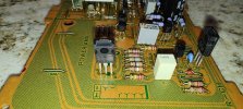
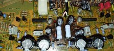
Decided to start with the differential amplifier board. F3975

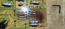
R24 was burnt; KD4 (MV103) voltage drop was off (measured 1.1V) should be close to 1.65 (3 diode drops). Made a decision to replace all transistors, upgrade the wattage of R3 to 3W as these run hot.

Q1/Q2/Q5: KSC1845F
Q3/Q4: KSA992FBU
Q6: KTA1381Y (KEC)
Q7: KTC3503Y (KEC)
C5/C6: Used 5P/100V COG
DZ1/DZ2: Upgraded to 1.3W 2% type
C4/C5: Upgraded to 470uf/63v
VR1/VR2: Multiturn pots (TE Connectivity)
kD3/D4: MV103 --> HLMP-K101 (Glows RED if amplifier is functioning normally. Great troubleshooting visual indicator!!

NOTE: Q6/Q7: Crucial to use transistor with low COB. If you cannot source suitable replacements and the installed transistors test OK, leave them alone.

IMG_20260822_213851770.jpg

Note the nice red glow (left channel visible) of MV103 replacements

IMG_20260826_184133011_HDR.jpg

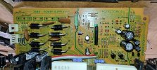
Next up F3989 - Protector circuit board

D1-D6: 600V/5A STT Fast Recovery Diodes
D9-D10: 1000V/2A Soft Recovery Diodes
Q5: KSC1845F
Q6: KSA992FBU
R15: Found 100R/2W resistor (Service manual calls for 82R 2W) --> Upgraded to 100R/3W resistor


All caps were changed along with small signal diodes to 1N4148

IMG_20260822_190102736_HDR.jpg

Next up F3977:

Installed new capacitors - same values except C6 which was upgraded to 100uf/50V
Re-flowed the VFD pins - found quite a few cold solder joints

IMG_20260822_214119416_HDR.jpg
 

Attachments

  • 1788154864673.png
    1788154864673.png
    424.9 KB · Views: 5
  • IMG_20260822_213914129.jpg
    IMG_20260822_213914129.jpg
    163.7 KB · Views: 5
Last edited:
Next up: F3976

Power supply

mQ1/Q3: TIP41C
mQ2: KSA916Y (OK to use KSA1013)
mQ4: KSC2383
Zener Diodes upgraded to 1.3W/2% type installed off from the board for better airflow
R3/R4/R5/R6 -> Replaced due to exposure to excessive heat

NOTE: mQ1 was installed on a heavy duty heatsink mounted to the right side of F3976. MUST BE INSULATED FROM CHASSIS GROUND

IMG_20260819_181531705.jpg

IMG_20260827_144526985.jpg

Amplifier/Protector:

kQ9/Q10: TTC004B/TTA004B
kQ11/Q12: KSC2690A/KSA1220A (if originals are blown you can replace with TTAs, in my case the originals were blown and I had KSA1220A available so I used them here)
C8/C13: Bumped up to 22pf/100V COG (Miller cap of higher value to improve stability as KSA1220A/KSC2690A have higher FT)
C9/C10: Bumped up to 47pf/100V COG for stability

kQ2/Q3: KSA1015
kQ1/Q4: KSC1815
kQ13/Q14: KTC4370A/KTA1659A
kQ15/Q16: 2SC3519(P)/2SA1386(P)
All fusible resistors upgraded to MF types (ALL tested good but still decided to replace)
R10/R11: Bleeder resistors upgraded to 8.2K/2W Metal Oxide
R37/R38: Critical base resistors -> 4.7R/1W
Emitter resistors: Replaced with 0.33R/5W dual resistor


IMG_20260820_195043572.jpg

IMG_20260822_214100368_HDR.jpg

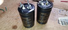
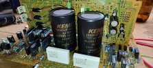
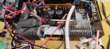
For main filters: Used KEMET 10000uf/63V 30mm diameter caps (Note: you cannot use anything more than 30mm here due to space). The mounting holes are non-standard. See picture on how I adapted to fit these caps

IMG_20260822_193001735.jpgIMG_20260822_194053216_HDR.jpg
 
Last edited:
Next up: F3981 EQ Board

M5220L IC was removed. Installed 8pin SIP socket and used SIP8/DIP8 adapter from Cimmaron Tech. Note the rail voltage to the opamp is +/-20V. Sansui uses this rail to power the VFD. Used 5532DD (low noise version) here for now. Need to explore the possibility to add a LM317/LM337 board to drop the voltage. Not critical as I don't plan to use a TT for critical listening. Power rail filter caps upgraded from 10uf/50V to 100uf/50v. Used Rubycon TWL LL caps for 10uf/50V X 2 for 4.7uf bipolar caps. Did not have 4.7uf film caps in stock so settled for the Rubycon TWL series.

IMG_20260825_224409219.jpg

F3979: The Incandesent bulb was replaced with 12V 70mA dash indicator bulb from Amazon. Installed a blue cover to maintain color.

IMG_20260823_100348168.jpg

All the wire harness along with the headphone jack is attached F3978

IMG_20260823_100337172.jpg

All switches and pots cleaned and lubricated while I had all the boards out. The TONE IN/OUT switch is critical as it is part of the feedback circuit. Disassembled and cleaned this switch.

Ready for Assembly:


0. Chassis prep by repainting the transformer (Did not like the color so changed it to Titanium Silver metallic!!) and install new power cable. Very easy to do with the back panel removed.
1. Mount all the boards that attach to the front panel
2. Install F3989 to F3976
3. Solder all wires
4. Install the front panel along with F3969 to the main chassis.
5. Install the EQ board
6. Install the back panel
7. Install the power transistor sub assembly
8. Install the heat sink

Recommend following this order of assembly.


IMG_20260823_191811961.jpg

IMG_20260824_151945418.jpg

IMG_20260824_174648989.jpgIMG_20260825_235421199.jpg
 
Last edited:
Final Steps....

1. Powered up on DBT. No smoke but no relay either.
2. Left channel had -40VDC at the output. Right channel was OK.
3. Right channel bias and offset adjusted to spec no issues
4. Triple checked all connections, transistor, diode orientation including MV103 that was changed -OK
5. Triple checked all fusible resistors - OK
6. Started comparing voltages at the FET between L/R channels
7. Found a short on the Left channel dual FET (UPA68H) between pins 6 anf 7
8. Replaced the FET (lucky I had a UPA68H L grade in stock from previous pull)
9. Issue resolved and was able to adjust both bias and offset to spec
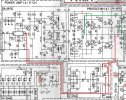
10. Feedback marked in RED and SFF (Super Feed Forward) marked in Green - see first attachment

THE SOUND....

1. Crystal clear highs with tight bass - beautiful sound
2. Quickly reminded me of my AU 519 - detailed and fast
3. Tone controls (I don't use) works but best left disengaged including the loudness switch
4. Compared to the AU 317, this one sounds slightly different - I would say has more detail
5. I still prefer the sound from my fully restored AU 317 (subjective)
6. Very low noise floor - ZERO noise from speakers at full volume (AUX/TUNER inputs selected with no signal) . It is DEAD QUIET

Final thoughts on the restoration

1. This is a complex restoration - definitely not for the novice
2. I don't recommend attempting restoration without full disassembly
3. Flat cables including the notorious flat black cable are fragile after 43+ years
4. Construction is typical 80s unit feel - plastic face plate/knobs
5. Toroidal transformer with dual windings - Nice
6. Part of bias spreader circuit is completed through 4 conductor flat cable - HUH - poor design
7. Sansui decided to split the Differential amp and Driver stages on two boards adding a lot to the complexity - poor design
8. Very happy with the choice of the transistors I made. The KEC transistors in VAS and Driver stages works beautifully (No issues with bias)
9. I like to implement @Leestereo style upgrades - was possible but limited due to space constraints
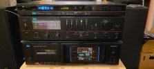
10. A fun project - enjoyed working on this. Will be used in my office connected to my DAC as desktop amplifier replacing the AU217 for now
11. VFD meters are nice with beautiful ambient lighting
12. Ah - The Sansui glue - absent here except under the main filters. It was a bear to clean up though

IMG_20260827_181235086.jpg

IMG_20260827_181004082.jpg
 

Attachments

  • Feedback and SFF.jpg
    Feedback and SFF.jpg
    213 KB · Views: 7
Last edited:
Great write-up. What a cool amplifier. The 80's look and colors grow on me more by the day. I haven't heard this particular amp but I have heard quite a few that are directly adjacent to it - these do sound clear, tight and solid. Really enjoyed your post. Hopefully you come across more obscure 80's Sansui that need to be saved :).
 
Last edited:
Nice work. I have been on the lookout for a clean one of these.

I have a Z-5000X with SFF, and assume the AU-D55X would sound similar.

Rob
 
Back
Top Bottom