• The move to the new server is done. There are some software and database maintenance updates in process. This has us passing the hat around to help out. We appreciate any donations. Seriously, even a dollar helps. The payment page may be found here - https://www.audiokarma.org/support.html

Sansui AU-X901 for restoration

Hyperion

Roobarb & Custard
Subscriber
Next up is an AU-X901 from Tony (@sansui au719 ) in his initial listening tests he was very happy with how it sounds, but he knows it has the 'glue' problem, and wants it to work reliably & better if possible - hence the reconditioning request.

Opening it up for a look inside and well, it's very dirty, :) there is also some brown smeary stuff that looks like flux residue on some parts of the chassis and the main amplifier board is covered in sandy coloured grime. Everywhere inside there are thin straw like fragments which I think are dried up flower petals. The glue is very dark brown and not too widely spread, but has damaged some components.

Yesterday I got round to giving it a check over, and found DC offset was 200mV+ on one channel and around 50mV on the other, bias was set (or had drifted) to very low levels around 1mV or lower for each of the 4 settings. So I reset the these as best I could with the old trimmers and had a listen, sounds nice but lacking that top end clarity and dynamic feel that I know it is capable of. Interestingly I find the only thing obviously wrong is that the 'Speakers B' selector switch works - but no relay click, ('Speakers A' works fine), I file that away in my mind for future investigation.

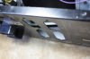
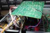
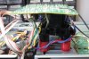
So I begin dismantling the amplifier because I want to completely remove the main amplifier board to clean it properly, and the heatsinks so I can re-do the bias tracking transistor mounting which looks a mess. I get to the rear panel and start removing screws - then a fragment of black plastic falls out of the unit. More screws removed - and then I notice it, a crack in the protection board! Further dismantling reveals that this amplifier has had a big impact to the speaker terminals, which has bowed in the rear panel, cracked the protection board, and bent the speaker terminal connecting posts like bananas. :(

I'll take some pictures and post them up so you can see for yourselves.

I think I can repair this, :thumbsup: but I need to remove the speaker terminals from the board so I can get a proper look. ;)
 
Last edited:
Register to hide this ad
Next up is an AU-X901 from Tony (@sansui au719 ) in his initial listening tests he was very happy with how it sounds, but he knows it has the 'glue' problem, and wants it to work reliably & better if possible - hence the reconditioning request.

Yesterday I got round to giving it a check over, and found DC offset was 200mV+ on one channel and around 50mV on the other, bias was set (or had drifted) to very low levels around 1mV or lower for each of the 4 settings. So I reset the these as best I could with the old trimmers and had a listen, sounds nice but lacking that top end clarity and dynamic feel that I know it is capable of. Interestingly I find the only thing wrong is that the 'Speakers B' selector switch works - but no relay click, ('Speakers A' works fine), I file that away in my mind for future investigation.

Opening it up for a look inside and well, it's very dirty, :) there is also some brown smeary stuff that looks like flux residue on some parts of the chassis and the main amplifier board is covered in sandy coloured grime. Everywhere inside there are thin straw like fragments which I think are dried up flower petals. The glue is very dark brown and not too widely spread, but has damaged some components.

So I begin dismantling the amplifier because I want to completely remove the main amplifier board, to clean it properly, and the heatsinks, so I can re-do the bias tracking transistor mounting which looks a mess. I get to the rear panel and start removing screws - then a fragment of black plastic falls out of the unit. More screws removed - and then I notice it, a crack in the protection board! Further dismantling reveals that this amplifier has had a big impact to the speaker terminals, which has bowed in the rear panel, cracked the protection board, and bent the speaker terminal connecting posts like bananas. :(

I'll take some pictures and post them up so you can see for yourselves.

Nice investigation you have done so far.
Nice Write up.
Am sure you will make it better than new again. :thumbsup:
 
Some pictures :(

Dented Rear Panel
IMG_3409a.jpg

Cracked Protection Board.
IMG_3411a.jpg

Bent Speaker Terminal Posts.
IMG_3412a.jpg

Update:
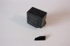
It's all under control, I have removed the speaker terminals, and discovered one of the relays on the board took most of the hit, which is good as I was very likely going to replace them anyway. The speaker terminals are OK, and apart from that one relay and the PCB nothing else appears to have been damaged. ;)
 
Last edited:
I have straightened out the rear panel, and the speaker terminal posts, and I have repaired the tracks in the board.

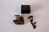
The sacrificial relay
IMG_3415a.jpg

Completely smashed
IMG_3416.JPG

Now, where was I... Oh yes! Main Amplifier Board removal ! :D
 
Last edited:
John, you were lucky I cleaned it up a bit. The story I was told was the guy's old father kept it in his room, next to his plants. I didn't ask, but the fact of its sale suggests the old Spanish gentleman may have breathed his last.

I'd like to think he died happily, transported by the music of Señor Sansui back to his youthful memories of dark haired beauties, in long swirling dresses, dancing to the sound of castanets and flamenco guitars.

Of course, it's more likely a nurse knocked the X901 over while watering the plants, the relay was smashed as it hit the floor and blew the speaker with a loud pop, like a gunshot, causing the old man to die of a heart attack.

The X901 as I received it

Sansui au-X901 dirty.jpg
 
Is this also like the au D11 ll and D77X, and I think the au Gxx series, where there is no chassis, just the four sides holding the PCB's? I can see in photos that at least the sides are from metal. On the D77X the sides are connected to the front with a kind of plastic click system that I still haven't figured out.
Would love to see some photos.
Are you going to upgrade the equilizers opamps like in your au D11 ll?
Just going to have patience then.
 
Last edited:
s this also like the au D11 ll and D77X, and I think the au Gxx series, where there is no chassis, just the four sides holding the PCB's? I can see in photos that at least the sides are from metal.
No, this and the AU-X701 have a pretty solid chassis, this layout & method was used and improved upon with many of the later models including the 'Alphas'. Becoming more symmetrical and 'balanced' with the transformer and PSU in the middle flanked on either side by the left and right output modules.
Would love to see some photos.
There will be pictures, I am just waiting until I can show you a finished board - which won't happen until after the Mouser order arrives.
On the D77X the sides are connected to the front with a kind of plastic click system that I still haven't figured out.
It took me a while to understand them on the AU-D11 II, actually it's been so long since I have needed to unclip them I've forgotten exactly how :D - they are quite easy once you understand the trick.
Just going to have patients then.
Patience is a virtue. :thumbsup:
 
Last edited:
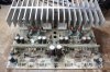
Here is a 'before' picture of the Main Amplifier board.

IMG_3419a.jpg

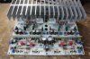
And now component changes (and a good clean up) complete - ready to be re-installed.
IMG_3422a.jpg

Parts replaced.
VR1 (x2),100Ω Trimmers - replaced with 100Ω Bourns 3296Y 25 turn trimmers.
VR2 (x2), 500Ω Trimmers - replaced with 500Ω Bourns 3296Y 25 turn trimmers.
VR51 (x2 & VR52 (x2), 1KΩ Trimmers - replaced with 1KΩ Bourns 3296Y 25 turn trimmers.
C2 (x2), C3 (x2) 4.7µF 50V electrolytic - replaced with 4.7µF 63V WIMA MKS2 Film capacitors
C4 (x2) 220µF 50V (!) - replaced with 220µF 10V Panasonic FR.
C33, 33µF 35V - replaced with 33µF 35V Panasonic FC
C51 & C52, 470µF 50V - replaced with 470µF 63V Nichicon PM.
C53, 100µF 25V - replaced with 100µF 50V Panasonic FM.
C54 (x2), C55 (x2), C62 (x2), C63 (x2), 100µF 50V - replaced with 100µF 63V Nichicon PM. (NB: Schematic says 220µF 25V)
R76 (x2), R77 (x2), R78 (x2), R79 (x2), 4.7Ω ½W Mox resistors - replaced with 4.7Ω ½W Metal Film.
DZ51, 22V 1W Zener Diode, replaced with 22V 1W Zener Diode.

Glue damaged parts.
R21 (x2), R22 (x2), R25 (x2), R26 (x2), 47KΩ ¼W, replaced with 47KΩ ¼W Metal Film.
R53, 470Ω 2W Mox resistor, replaced with 470Ω 2W Mox resistor.

You might notice at least one of the trimmers is installed at a slightly 'jaunty' ;) angle - this is because they are very close to adjacent components.
 
Last edited:
Ah, first views of your work. Did you change out Elna silmic? Or where there UCC in there? Doesn't look like you went up much or any in capacitance.
A lot of trimmers to replace on these. When you're going to set her up in the end you're going to try the method of Bumpalump for hot to ground, to see how that works? Would be really interesting. I would like to try it on my D77X and B 2102. So may be will put them on the bench for a day, a good excuse to finally by some more dmm's.
 
Last edited:
Have to say, Sansui really took out all the fanciness for the international models. No copper nowhere, really sober insight. Looks like they really just tried to compete on price and didn't know the market. I can remember the Accuphase amplifiers in early 90's in my local hifishop. But no Sansui's there. Sad, I would have been in the market for this amplifier for sure.
 
The Main Amplifier board is back in the unit, and has tested OK - DC-wise.

Also, I now get a nice 'ping' from both speaker relays now - so the protection board is OK too. ;)

Post #15 updated with replacement component information.

Component change details for F-5639 Protection Board.
C1 (x2), C2 (x2) 100µF 10V Bipolar, replaced with 4x 100µF 16V Nichicon VP.
C4, 1µF 50V BP - replaced with 1µF 63V WIMA MKS2.
C3, C6, 1µF 50V - replaced with 1µF 63V Panasonic FR.
C8, 33µF 10V - replaced with 33µF 25V Panasonic FC.
C9, 0.47µF 50V - replaced with 0.47µF 63V WIMA MKS2.
C10, C11, 4.7µF 50V - replaced with 4.7µF 63V Panasonic FR.
C1,(?) 220µF 25V - replaced with 220µF 35V Nichicon PM. (marked on schematic as 100µF)
C1,(?) 100µF 50V - replaced with 100µF 63V Nichicon PM.
RL1 & RL2, Matsushita 'JC2aD-DC24V' - replaced with Omron 'G4W-2212P-US-TV5-HP'
 
Last edited:
Have to say, Sansui really took out all the fanciness for the international models. No copper nowhere, really sober insight. Looks like they really just tried to compete on price and didn't know the market. I can remember the Accuphase amplifiers in early 90's in my local hifishop. But no Sansui's there. Sad, I would have been in the market for this amplifier for sure.

Bear in mind that the AU-X701 and AU-X901 are the equivalent of the AU-a607i and 707i which were also not particularly fancy inside. Only the big-daddy AU-a907i had top-quality internals, and there was no international equivalent of this model - it was manufactured for the Japanese market only.
 
Back
Top Bottom