• The move to the new server is done. There are some software and database maintenance updates in process. This has us passing the hat around to help out. We appreciate any donations. Seriously, even a dollar helps. The payment page may be found here - https://www.audiokarma.org/support.html

Sansui AU-X901 for restoration

I think I had the timeline mixed up a little, don't even know if they where out by that time already.
Looks like the x901 came out in 1987 already and the x911 in 1989. I thought they where from 1990-1995. Updated my Sansui history knowledge base.
Correct. This particular one has serial number 438082957, so August 1988.
 
So, I had a bit of a session today with an intermittent fault that was putting the amplifier in protection mode briefly, and then recovering as if nothing had happened. A combination of noisy MV103's, and troublesome 2SA1145//2SC2705 pairs was to blame. ;)

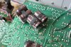
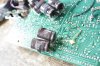
Also I've been tackling the Control Amp, here is a couple of views of the track side where I found these apparently late additions. Not too worried about the resistors and the film capacitor, but those huge electrolytics need something done with them. ;)
IMG_3425a.jpg

Another view
IMG_3426a.jpg

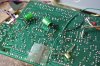
I find that the four capacitors in the lower picture form 2 bipolar capacitors, and I can't see that they need to be 50V rating each - a combined rating of 100V, so I replaced them with quality bipolar capacitors, with the board now looking like this. (I'll put some self adhesive foam on the new bipolars to cushion them against the underside of the PCB. ;) ). The original topside positions for these capacitors are marked, but don't now (if they ever did?), have the correct track pattern//connections to allow possible mounting on the topside of the PCB.
IMG_3427a.jpg

The two capacitors that were mounted in the centre foreground (on the plastic pad) have been replaced with same value/voltage capacitors, but now located on the component side of the board in their provided locations. The originally fitted capacitors were too big to be accommodated in their component side positions - presumably the result of component shortages all those years ago. This is also borne out by the original use of 220µF 50V capacitors on the Main Amplifier board where 220µF 10V (or 16V), was the correct component - because it is placed across a 6.2V Zener diode.

You might be able to see a rounded blob of something underneath the remaining plastic capacitor mounting pad in the last picture - this is some kind of hot glue, almost clear but with a milky appearance. I needed to remove the upper 2 blobs & pads, because there were capacitors on the topside that had to be changed, but this is really tough stuff and wouldn't come off. So I after some chin scratching I decided to try 'silicone shower sealant remover' - it worked! - I decided to leave the last bit as an indicator of what had been there for a future restorer. ;)

Component change details for F-5643 Control Amp PCB.
C13, C13, C23, C24 (x2) 4pF Ceramic, replaced with 4pF Murata MLCC C0G/NPO.
C16, C17 (x2), 220µF 50V, (bipolar pairs measured at ~105µF each) - each pair replaced with single 100µF 50V Nichicon ES Bipolar.
C36, C37 (x2) 10µF 25V, each pair replaced with 4.7µF 63V WIMA MKS2. (vacant position jumpered).
C41, C42, 220µF 35V - replaced with 220µF 35V Nichicon PM.

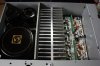
I have just been having a listen to the amplifier :music: before I deal with the last two items - The EQ Amp board, left until now because of so many connections, and the remote mounted metal tape driven switches, and the PSU because of the heavy duty soldering to the main PSU capacitors, also it is buried in a 'sea' of interlocking plates - awkward items to restore. ;)

Despite all my efforts to avoid it, I ended up having to de-solder the main PSU capacitors from the PSU board. I just couldn't get the access I needed to properly clean the glue off the PSU board. It all went well and I think I made a neater job of re-soldering the lugs of the capacitors. One thing that struck a chord with me, was that for example, the original two 1000uF capacitors on the PSU board appeared to be in excellent condition, and had me thinking I wonder why I am changing them. This echoes the sentiment expressed by AK member Bumpalump regarding some original capacitors which are still in good condition. The difference is I can't afford/justify an ~£800 (~$1120) piece of test gear to prove it. ;)

 
Last edited:
Nice write up. So in the schematic the 2 back to back capacitors are in there but on the board in the service manual not. Any guess what was the reason they added them later?

A combination of noisy MV103's, and troublesome 2SA1145//2SC2705 pairs was to blame
When you have the time I would love to hear how you found out these where the culprit. And what you did to solve the problem.
 
When you have the time I would love to hear how you found out these where the culprit. And what you did to solve the problem.
Nothing special here just educated systematic substitution. I already knew that the MV103's can be a problem, and after changing them for series sets of three 1N4148's it seemed better- but the problem was still there. So the next culprits had to be the known troublemaker 2SA1145's in particular, and their complementary friends the 2SC2705's, so I changed 2 pairs (in the faulty channel), and the problem went away. :) That's how it stands at the moment, only changed in one channel. But I'll be trying a set of different substitutes for these as the output capacitance of the current subs (TTA004B//TTC004B) is a bit higher than the originals at 17pF and 20pF as opposed to 2.5 pF and 1.8pF for the originals.
By the way, the actual problem was the 'Cold - Ground' offset being very unstable and very briefly going high enough to trigger protection, 'Bias' and 'Hot - Cold' offset as far as I could see, being completely unaffected while this was happening, which added to my puzzlement about what was causing it. :)
 
Last edited:
Had to check the service manual, 2 of them, from the x901 and D77X to know for sure which offset you where talking about;).
But I'll be trying a set of different substitutes for these as the output capacitance of the current subs (TTA004B//TTC004B) is a bit higher than the originals at 17pF and 20pF as opposed to 2.5 pF and 1.8pF for the originals.
Although I am assuming you will find one, I found this one adviced here on the Audiokarma: KSA1381 / KSC3503.
I see it's ok to substitute the MV103's with the 1N4148. Was under the assumption that you needed the 1N4150. I was looking for them but are impossible to find. Good to know. I was wondering already if the Sansui engineers wanted the exact voltage drop or this was just what they used and the 200 mV is irrelevant.
On a sidenote.
Looking at the schematic of the au D 77X the circuit is very, very similar. Next to a different control (preamp) section it's the same as the x701.
Still only thing I can read about is that it is considered a lesser Sansui, just based on looks/ build. I can understand that, like the au 717/719 comparison although there it's just the inside build quality.
Just to lett people know : if you want a poor man's au x701 you get really close with the D77X for like 35% of the investment, at least based on circuit topology and implementation.
 
Was under the assumption that you needed the 1N4150. I was looking for them but are impossible to find.
https://uk.farnell.com/vishay/1n4150-t-r/diode-small-signal-50v-do-35/dp/1612349

1N4150 have a slightly higher forward voltage drop, and overall their characteristics make them useful for matching the forward voltage drop of some multi-junction bias diodes. I measured the original MV103's in circuit - forward voltage drop of just over 2V, and 3 x 1N4148 - just under 2V at low current, but rising to just over 2V (in a test setup I used), when the current more typical in these positions is found. ;)

I have some 1N4150 (the glass version - that looks like 1N4148) - but I only have 4 :(

KSA1381 / KSC3503 is what I will be trying, but later on.

:)
 
Last edited:
Thanks for the link. I never check Farnell because I can't register. The form insists I give a VAT nr. But I don't have a company. But is good to know.
I see now mouser also sells them. Last week I was reading a thread about an Audiokarma member that went through the effort of comparing the diodes available to replace the mv103. He came up with the 1n4510 being a closer match in voltage drop. Then I could not find them.
But like I thought, it's not about the exact voltage drop. Approximately is good enough, I think at least.
 
This AU-X901 is finally finished. :)

IMG_3428.JPG

IMG_3430.JPG

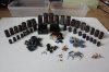
And the removed components. (note: shattered speaker relay ;))
IMG_3431.JPG

Component change details for F-5631 PSU Board.
C4, C5, 1000µF 50V - replaced with 1000µF 63V Nichicon PM.
C6, C7, 100µF 35V - replaced with 100µF 50V Panasonic FR.
C8, C9, 470µF 50V - replaced with 470µF 63V Nichicon PW. (schematic says 1000µF 50V).

Component change details for F-5690 EQ Board.
C1, 1µF 50V - replaced with 1µF 63V WIMA MKS2.
C6, 100µF 16V - replaced with 100µF 16V Nichicon PM.
C7 (x2), 47µF 10V - replaced with 47µF 25V Panasonic FC.
C10, C11 (x2) 10µF, 50V - each pair replaced with single 4.7µF 63V WIMA MKS2. (vacant position jumpered).
C14, C15 (x2) 220µF 35V - replaced with 220µF 50V Nichicon PM.
C16, 470µF 6.3V - replaced with 470µF 16V Nichicon PM.


Totals for replaced components.
64 Electrolytic Capacitors.
12 Trimmers.
9 Mox Resistors.
8 Carbon Film Resistors.
8 Transistors
4 Dual Diodes
2 Relays.
1 Zener Diode.
 
Last edited:
R76 (x2), R77 (x2), R78 (x2), R79 (x2), 4.7Ω ½W Mox resistors -
These are the output transistor base resistors?
I have seen you mention that you wanted to change them on one of your own amplifiers.
Desired effect: tighter tolerance brings more equality between outputs?
Looks good the amplifier! With an interesting start.
Did you change the tta/ttc004b out in the end?
 
Desired effect: tighter tolerance brings more equality between outputs?
No, they sound dreadful :) - like electrolytic capacitors, Mox resistors are sometimes a necessary evil, but not for base resistors - metal film are much better. ;)
Did you change the tta/ttc004b out in the end?
Yes I did, changed for KSA1381//KSC3503 ;)
 
Sorry for lack of pictures for the latter sections of the restore, - I have updated the relevant posts with the missing component change information for the boards with missing pictures. ;)

Post #18 = F-5639 Protection Board.
Post #23 = F-5643 Control Amp Board.
Post #31 = F-5631 PSU Board. & F-5690 EQ Board
 
This is remarkable restoration work John. I'm fortunate to live close enough to you to benefit directly from your talents but I'm sure many others will benefit from such an exhaustive rebuild, particularly anyone fortunate enough to own one of these lovely amps. Even in its orginal state there was a great sound coming from this AU-X901. I can't wait to hear it now that it's had your magic touch and I will be sure to post my impressions. Thank you for pouring both your intelligence and your passion into this project. I will pay you for the former but I appreciate you give the latter freely.
 
Thanks for this John, would you be able you share your BOM list (with MPNs)? I am about to recap my Alpha AU707 (100V version) which I do believe is the equivalent of AU-X901. Thanks in advance.
 
Last edited:
Thanks for this Pete,
Actually my name is John ;) and I am sorry I don't have a complete BOM & list of MPN's for this amplifier. I nearly always order more parts than I need for a particular amplifier, this means that the parts I use for a restore are split between those held 'in stock' and what I buy specially for a particular restore.
 
Hi John,

My bad :whip:, thanks for the reply :beerchug:
Cheers!

Actually my name is John ;) and I am sorry I don't have a complete BOM & list of MPN's for this amplifier. I nearly always order more parts than I need for a particular amplifier, this means that the parts I use for a restore are split between those held 'in stock' and what I buy specially for a particular restore.
 
Back
Top Bottom