• The move to the new server is done. There are some software and database maintenance updates in process. This has us passing the hat around to help out. We appreciate any donations. Seriously, even a dollar helps. The payment page may be found here - https://www.audiokarma.org/support.html

Sansui BA-F1 amp problem

RJ_Crafts

AK Subscriber
Subscriber
Hi AK members,

Got a unique problem with a Sansui BA-F1 amp.

I got it with the left channel blown for repair. Found outputs and drivers bad. Also R37, R42 burnt I replaced all the obvious bad components and powered up the amp. No issues and protect was off.

I adjusted the DC offset and bias. All was going well. I went to check power and distortion and R42, a 47 ohm resistor began to smoke at about 1/3 power. I shut down and rechecked outputs and drivers. All still good.

Unit still powers up not in protection, but when I up the level for output on left channel the R42, 47 ohm will heat up and burn if level not turned down.

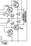
I have compared the LC to RC and see that the DC voltages listed on the schematic for the left channel change with the output level control. They do not change on the right channel. I have now recapped the driver board, pulled a number of transistors and can find nothing at fault. Yet, I cannot increase level without resistor burn.

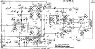
I attached a copy of amp schematic. Voltages at TR10 and TR11 emitter and base remain constant while increasing level. The voltages at collectors start correct with no output level on front panel. When I increase the audio level with front panel control the DC level at collectors increase, This dose not happen on the right channel. The DC values remain constant.

If anyone has a good theory why this might be happening, would appreciate the help. Screenshot 2026-08-22 210702.jpg
 
Register to hide this ad
The first step is to let the group know what the original power output transistors were replaced with. The originals, same as on AU-919 were very unique, and contributed a great deal to the performance of the amp, so its important to put proper, and high quality substitutes in. As well as replacing all the trouble-maker 'black flag' caps.
 
The first step is to let the group know what the original power output transistors were replaced with
+1

so its important to put proper, and high quality substitutes in. As well as replacing all the trouble-maker 'black flag' caps.
+1

And also not to mix old and new replacement Output or Driver transistors in the same channel. Double check orientation of all replacement transistors and values of replacement resistors, assume nothing.

If you don't find anything - test/replace TR13 & TR15, and if you still have problems, do the same for TR12 & TR14.
 
Last edited:
The first step is to let the group know what the original power output transistors were replaced with. The originals, same as on AU-919 were very unique, and contributed a great deal to the performance of the amp, so its important to put proper, and high quality substitutes in. As well as replacing all the trouble-maker 'black flag' caps.
Hello and thanks for the reply.

The original outputs, NLA, were NMC1012 and NMA1012.
I researched posts on AK and found acceptable subs were 2ST5949 and 2ST2121. Went to Digikey website and found these to also be obsolete. The recommended
Digikey replacements were MJ21195and MJ21196.

I also replaced the drivers TR10 and TR11, were 2SA939 and 2SC2071 with MJE15032 and MJE15033 replacements. Also had to replace R37,R40,R42. Burnt .
The first step is to let the group know what the original power output transistors were replaced with. The originals, same as on AU-919 were very unique, and contributed a great deal to the performance of the amp, so its important to put proper, and high quality substitutes in. As well as replacing all the trouble-maker 'black flag' caps.
 
The first step is to let the group know what the original power output transistors were replaced with. The originals, same as on AU-919 were very unique, and contributed a great deal to the performance of the amp, so its important to put proper, and high quality substitutes in. As well as replacing all the trouble-maker 'black flag' caps.
Hello and thanks for the reply.

The original outputs, NLA, were NMC1012 and NMA1012.
I researched posts on AK and found acceptable subs were 2ST5949 and 2ST2121. Went to Digikey website and found these to also be obsolete. The recommended
Digikey replacements were MJ21195and MJ21196.

I also replaced the drivers TR10 and TR11, were 2SA939 and 2SC2071 with MJE15032 and MJE15033 replacements. Also had to replace R37,R40,R42. Burnt .
I also recapped the driver board with the exception of C01 and C02. They measured OK with cap meter and PS rails looked OK
 
+1


+1


And also not to mix old and new replacement Output or Driver transistors in the same channel. Double check orientation of all replacement transistors and values of replacement resistors, assume nothing.

If you don't find anything - test/replace TR13 & TR15, and if you still have problems, do the same for TR12 & TR14.
Hello Hyperion
Thanks for the reply. Old and new parts not mixed. replaced in pairs, TR13 and TR15 were replaced with MJE15032 and MJE15033 transistor subs.
I will look into replace of TR12 and 14.
 
If you wired everything correctley then I suspect you might be dealing with oscillations. Do you have oscilloscope ?
 
I located the original problem. Turn out, I had 2 bad .33 ohm 5W emitter resistors that went bad. I replaced all 4 emitter resistors to be on the safe side.

Now I can't set the bias adjustment. It just reads zero volts. I have verified VR02 is working. I can see voltages change at D03 and D04. I have pulled and tested Tr10,11,12,14.

I earlier replaced TR13 and TR15 with MJE15032/15033 transistor as subs. Below is the adjustment procedure per manual.

I have checked R37,38,39,40,41,42,43,44,45,46,47. All look good.
R37,R39 and R41 were replaced earlier as they were visibly burnt.

Even though I cant read / set bias to the 20mv per manual, unit is not in protect mode and I can put a signal into the channel and get amplified reading on scope into an 8 ohm load.

If anyone can help with this I would appreciate it. I seem to have run into a wall and maybe over thinking or overlooking something.

TIA

Rick
Bias adj BA-f1.jpg
 
+1


+1


And also not to mix old and new replacement Output or Driver transistors in the same channel. Double check orientation of all replacement transistors and values of replacement resistors, assume nothing.

If you don't find anything - test/replace TR13 & TR15, and if you still have problems, do the same for TR12 & TR14.
Hello Hyperion,

I located the problem I mentioned earlier. I missed seeing that 2 of the .33 ohm resistors were open. I replaced all 4.

I see you have done a restore to one of these amps a few years ago. Found the thread.

When you did the restore and went to set the bias, did you have any issues with the procedure in the manual? as reading the 20mv at the location in manual prior to replacement of the defective resistors. Now when I check the location noted in the setup, I read 0 volts. I have checked the bias adjust pot and it is working.

The right side was working ok and I did some non powered up checks with a Huntron tracker and ohm meter. I notice what I thought was a problem. On pin 7 to 8 of left amp I read about 10 ohms. Did not get same reading on right side. I pulled the right side driver board and found pin 7 had bad solder connection making it an open connection.

I fixed the connection so pin 7 made connection with R45, the 4.7 ohm resistor. I went back to check bias on right side and it now read 0 just like left side.

I am able to get audio through the amp and both relays click and it is not in protect mode and no DC offset.

Do you recall any issues with setting bias after restore?

TIA for any help
Rick
 
On pin 7 to 8 of left amp I read about 10 ohms.
Those two pins should read about 10Ω, because you are measuring the resistance of 2 x 4.7Ω resistors. I will say that this amplifier contains a lot of those matte-finish grey resistors, (like the original 4.7Ω resistors) stood up off the board with kinked leads. In my experience they can open while looking perfectly OK visually - they need to be checked if there has been any high current/shorted OP or driver transistor action. I replaced all of mine (in both channels) because of faulty output/driver transistors. I might say finding faulty solder joints at this stage should be an extreme rarity - a good close visual check and boards cleaned of flux are an advantage here. ;)

The key voltage to check is the voltage across C & E of TR01 (the bias transistor), you should see around 2-4V and it should be adjustable with the trimmer. The higher the voltage the greater the bias current. Check R37 & R38, 390Ω - they take a beating and can be high resistance.

In case you are not familiar with bias circuit action - The 2-4V is presented across the B-E junctions of TR12 & TR14 and TR13 & TR15 - turning them on, this voltage is in turn used to increase current flow (in stages), - eventually through R41 & R42 (47Ω ½ watt), increasing their voltage drop which goes onward to the B-E junctions of the output transistors gradually turning them on. Any faulty resistor or B-E junction, (or other transistor fault), will cause incorrect or zero bias - you have to check them all.

I had no problems that I can remember setting bias, if I did I would have mentioned it in my thread.
 
Thanks for the help.

I will check TR01 C to E. I did lose 2 4.7 ohm resistors, R37 390 ohm, and R39 560 ohm.
the procedure in the manual says to check emitter resistors R706 and R708 for adjusting the 20mv. Is the manual incorrect?

This is the spot I was measuring and unable to get bias set. Adjustment not working.


1788285183635.png
 
This is the spot I was measuring and unable to get bias set. Adjustment not working.
Yes, that's it, Service Manuals are sometimes inaccurate but not this time.

Remember you are measuring voltage in mV - not current, have you checked your meter is working ok?

Are you sure you have +/-56V ? (finding it a bit surprising that you can actually hear music through this :dunno: ).
 
Hi, I can set the bias and I did on the right channel. I can adjust the bias on the left channel, but still not measuring the 20mv.

The +/- 56v reads +/- 55 at the connector on driver board. I can also measure it on the collectors of the outputs.

I did measure RC and LC at the pins from driver board to outputs.

RC
Pin 5 0.556
pin 5 0.552
pin 7 -0.567
pin 8 -.564
Measured at emitters TR706/708 0.20v

LC
pin 5 0.428
pin 6 0.427
pin 7 -0.446
pin 8 -0.442
Measured at emitters TR706/708 0.00v

3 of the 4 original outputs were shorted. I went thru AK to locate subs. Eventually ended up with MJ21195/21196 as a sub from Digikey.

All 4 of the .33 ohm resistors were replaced. 1 was open and another read >60k

I do get audio out of both channels.

Thanks for the feedback

Rick
 
Is the BA-F1 more sensitive to lower impedance speakers, or are there components in the protection circuit that can be checked to make the amp more robust?

My F1 usually runs well, though it does get somewhat hot when playing music for a while, the black flag caps were removed.

But I have observed when playing cd's, that here & there, it has shut off into Protect mode, though it will turn back on and run ok again.

I try to find the ideal volume level between the controls on the CA-F1 preamp and F1, if that might affect the protection circuit. In other words, I try to
keep the F1 meters from going too far into the red zone. I suppose the meters tend to read high since they were calibrated for 8 ohm speakers, not 4.
I dont play too loud, but if the amp pauses into protect mode, and I restart it again, I will lower the F1 volume down to about 5 or 6 (halfway) and raise the
volume knob on the CA-F1 preamp. (as opposed to having it on 10 max on F1, and lower on CA-F1).

I find it interesting that my G-9000, a mere "receiver" can outperform a dedicated power amp, but I have never had the G-9000 ever go into protect mode as the F1
has. I realize the G-9000 is 160 and the F1 is 110W, but despite the wattage difference, I dont think it would matter too much in terms of volume level.

The G-9000 power meters dont seem to go very high at all, and the G-9000 can play loud with its volume on about 40 (or 4 if the range is 1 to 10, or 40 if range is 0 to 100), basically the G-9000 is loud without needing to ever go near or past halfway on the knob.

Thus, I wonder if the protection incidents has to do with the design of the amp itself, or if its my own F1 and some components in the protection circuit might need to be replaced. I am also curious if the AU-919 has the same protection circuit as the F1, as they have the same unique power out transistors, so I think of the F1 as a 919 in power amp form, except that the F1 has meters to give me visual indication that the 919 does not have, and an extra set of (separate left & right) volume controls.

If anyone has some insight to share, I would be interested to hear, thanks.
 
Hi again,

Yes on the V C to E. Variable 2-4v and all the resistors in question have had a leg pulled and verified values.

I am beginning to think the substitute components i used are not compatible with this circuit. I have researched DIYA and AK for subs, but al i can fand are now obsolete. Do you have and recommendations for current replacements of the outputs NMC and NMA1012's and the drivers 2SC2238 and 2SA968 that would work better?

TIA

RIck
 
Follow up. I am able to set bias on LC up to the pins 5,6,7,8 that match the levels on the RC.

I believe the MJ21195/21196 transistors are not getting enough to turn on. This could be why when I applied a signal, the amplitude generated is enough to turn on the outputs. Both sides work OK at about 40 on the panel scales. same amplitude and no DC offsets.
 
You must be missing something. I think you must still have damaged components from the original 'blow-up' that you haven't found yet. If those output transistors are not turning on that must be the reason, it's obvious from your voltage readings. Unless you are also measuring bias on the wrong points for the left channel.

Sorry to be so blunt with you about this, but sometimes a little of that forces assumptions to be challenged, but in a good way. ;)
 
Last edited:
Back
Top Bottom