• The move to the new server is done. There are some software and database maintenance updates in process. This has us passing the hat around to help out. We appreciate any donations. Seriously, even a dollar helps. The payment page may be found here - https://www.audiokarma.org/support.html

Sansui G-5700 no sound

so sorry .the manual i have covers the 5700 6700 and 7700 .i was looking at the 7700 .
r58 is the same
the pins are different on the board and its number should be f-3093 .
pins to check are 6 and 4 ..3 and one . or pins on the driver board 54 and 58 . 60 and 64 ..
ok i am going to upload the diagram .
use ctrl+ to make it big enough to see then look at the bottom right . this is where the problem is .
to save any confusion its going to be easier to remove the power transistor board . it look like 2 screws to me ..
be very careful with d601 on that board .you don't want to break its leads off at all costs . its an stv3h and very hard to find a replacement . its horseshoe shaped .
 

Attachments

Last edited:
Pete: It might be easier for him to probe at the jumper connections rather than remove the OP TR boards. Just tell him what color wire.

This should be done with power off.
.
 
Pete: It might be easier for him to probe at the jumper connections rather than remove the OP TR boards. Just tell him what color wire.

This should be done with power off.
.

no wire colours mentioned in manual . and its not easy comparing pictures with a really badly copied scan of the board in the manual . will try and decipher it all in a bit .
numbers should be 321645 with the wires at the top as installed in amp
ignore middle 2 as they go to stv3h diode . also the wire at lower middle looks like it goes to pin 3
 
Last edited:
DEFINITELY NO POWER UNTIL ITS DIAGNOSED
as a precaution before doing any tests set meter on 200v dc ..one lead on unpainted chassis the other to each of the wires on the power transistor board . if all 0v its safe to proceed
ok it should be easier this way . the transistors are BCE but are upside down so as they are they are ECB looking from the front of the amp .
it looks like you can see down the back of the board to see the transistor pins . we are interested in looking for short circuit between C and E on each of them transistors .
so looking down on the transistors its left pin and centre pin .one probe on each .meter on 200 ohms .
 
Last edited:
ok I think I did what I was suppose to do I tested all four transistors and the two on the left came up about 23, then the third from the left was all over from .003 to 59, and the fourth from the left was 16 ohms... I don't know what they were suppose to be I was a little confused by all the back and forth conversation...
 
ok I think I did what I was suppose to do I tested all four transistors and the two on the left came up about 23, then the third from the left was all over from .003 to 59, and the fourth from the left was 16 ohms... I don't know what they were suppose to be I was a little confused by all the back and forth conversation...


it is looking like you need to remove the transistors for a proper testing as other things in the circuit can throw things out .
as i stressed before be very careful with them diodes that are bolted to the heatsink above the board with 2 wires .
take your time to avoid any mistakes .
mark which transistor went where its very important .
my next post will be a diagram with instructions how to test transistors
 
their are four main transistors with heatsinks on them that I tested before or their are a bunch of small ones but all the numbers you are referring to are not labled anywhere around or on all the transistors. I don't know what to test.
 
their are four main transistors with heatsinks on them that I tested before or their are a bunch of small ones but all the numbers you are referring to are not labled anywhere around or on all the transistors. I don't know what to test.

The large output transistors, there are two per channel.
There is 1 x 2SA1105 and 1 x 2SC2580 per channel, the numbers will be on the black silicon body....
These are the ones to test.....Search and download the datasheet so you get the pin-out correct....then proceed to test them....

If you are taking those large output transistors out and off the little circuit board, be VERY VERY careful you do not break the wires off the little STV-3H thermal diode which is also attached to the heatsink and the circuit , if you do, then forget the project, you have a large paper weight.....these are VERY difficult to find....
 
their are four main transistors with heatsinks on them that I tested before or their are a bunch of small ones but all the numbers you are referring to are not labled anywhere around or on all the transistors. I don't know what to test.

i was referring to the ones you tested .the readings aren't making sense so they need unsoldering from the boards .
 
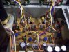
sorry I am confused, I uploaded a pic of what I think im suppose to test but all the numbers I have been given are not the number written on the transistors... I don't know what to be careful of because I cant see a diode anywhere... hope the pic helps
 

Attachments

  • 100_3350.jpg
    100_3350.jpg
    95.4 KB · Views: 51
ok i will explain the best i can it would take me ages plus swearing to mark pictures ..
see the big piece of metal standing vertical at the back ? there are 2 circuit boards with wires these have the power output transistors attached to them .above each board is the diode screwed to the metal .these are to be handled with great care .
its the board on the right we are interested in . it looks like 2 screws hold it in place and 1 screw for the diode . unscrew the diode first to save damaging it .leave all wires attached to the board . if it feels safer for you to unsolder the diode for now then mark the leads as it has to go back the same way round .
then you need to unsolder the transistors for testing . i use a solder pump . others use desoldering braid .its whatever works best for you .
 
ok I get exactly what your talking about now, THANKS!!!!. I tested both transistors on the board the leads E and C. both came up at about .0-.1 ohms mostly .0. do you still want me to take them off?
 
yes they look shorted or something else is shorted .. only way to tell is remove them
top tip hold meter leads together see what it reads ..that is short . it will help us both to know how your meter works /is calibrated ...
 
I put the tip of my meter together and it read 0 ohms. I also desoldier the components and they both read 0 ohms on leads C and E. I hope this is good news!
 
that means they are shorted .just to make sure try the other 2 transistors that are are the other little board .no need to remove them .
you will also need to test some more transistors on the large board .they are the ones you marked on your picture .
 
ok, all the transistors measure about 25 ohms, except the left and right one on the big board, I could not get a good reading on those, they were either OL on my multimeter or they were all over the charts
 
ok .it would be best if you pulled and tested the 2 on the right that are bolted to the U shaped heatsinks . tr16 tr18 ..and tr20 ...tr20 is a small transistor that sits midway between tr16 tr18 towards the front of the amp . .
here is pic i was kindly sent from a fellow ak-er . it is marked where the transistors are soldered to on the underside of the board .http://i1110.photobucket.com/albums/h453/ghazzer/F2980XRay-006A_zpsdfe14fda.jpg
tr16 is NPN ...tr18 PNP tr20 PNP
looking at the writing side pins down . tr16 tr18 is BCE tr20 is ECB
 
Last edited:
what pins would you want me to test?

the 6 way test that's in the thread i posted ..this is after them 3 transistors are removed from the board ..
i don't know if your amp has a removable access panel underneath or not ?
if not you will have to work out how to get the board up to de-solder them 3 transistors . it should come up with all wires attached .
 
Back
Top Bottom