• The move to the new server is done. There are some software and database maintenance updates in process. This has us passing the hat around to help out. We appreciate any donations. Seriously, even a dollar helps. The payment page may be found here - https://www.audiokarma.org/support.html

Sansui R-30 Speaker switch!

EduardoAguiñ

New Member
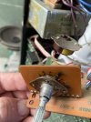
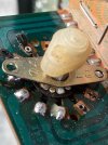
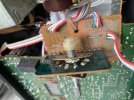
I bought this R30 because someone had knocked the speaker selector.
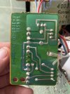
Opening it I realized that the contacts in the switch are broken so it does not make contact.
Any idea how I should bridge the switch by wiring it or ideas on how to restore the tracks?
 

Attachments

  • image.jpg
    image.jpg
    115.9 KB · Views: 14
  • image.jpg
    image.jpg
    93 KB · Views: 13
  • image.jpg
    image.jpg
    113.9 KB · Views: 13
  • image.jpg
    image.jpg
    96.6 KB · Views: 14
Register to hide this ad
Presumably one of those 3 wire red, white & blue cables goes back to the power amp section and the other two go to the speaker output jacks. Trace which one is which, then install jumpers on the board from the amp wires to the speaker 1 jack wires of the same color.

If you need it, the service manual is available on HiFi engine. If you don't have an account, PM me and I can email it to you.
 
Thank you ! I tried to download the SM, but they are not accepting any more new accounts.
would you mind throwing more light on how to bridge them?
on the first picture, the cables on the right are actually the ones that go to the headphones.
So I guess that these are the colors for the audio cables.

#40 white/blue,
#41 solid white
#42 red

On the top part of the first picture, you can see those colors, plus a yellow/white wire, which is the one that goes to another board (#39 on the PCB)...

I appreciate all the help you can give me.
 
Thank you for the manual. The schematic is missing one wire though...
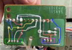
I followed the tracks and could figure that these tracks are all connected and also make contact with bridges on the other side of the PCB:

I would like to guess that the switch only makes them contact with the same colors on the other side of it. But I am still afraid of creating a short circuit by bridging them!
I am guessing the yellow wire is ground for system B and White is for system A... who knows? this is a nightmare :)
1736201676871.png
 
At this point, your best bet is to trace the wires back to their other ends and see what each color connects to. Since you said one goes to the headphone jack, that wiring is standard, so if you can determine which one goes to tip, ring and sleeve, you can figure out what each wire does.
 
Back
Top Bottom